1. Introduction and Goals
-
LoMap is a decentralized web application where citizens will be able to check personalized maps filled with their city’s places and shops.
-
Our goal is to provide Brussels' citizens the most useful and secure application to keep and share their favourites places such as restaurants, shops, monuments and more.
-
We have also the objective of creating a general software solution for every city around the world that could need our app.
1.1. Requirements Overview
| Name | Description |
|---|---|
Adding places on different tabs |
Users can add different kinds of places (shops, restaurants, monuments, landscapes…) |
Map visualization |
Users can see places on a map |
Reviews |
Users can add punctuations, comments, photos and more to added places |
Privacy |
A user can customize the way of sharing information with other users |
Decentralized information |
Each user has a unique pod for its personal information |
Social interaction |
A user can see other user’s places and reviews |
App options available |
There are filters for categories, friends and more |
| Name | Description |
|---|---|
User roles |
There will be roles: citizien, clothing shop, restaurant, bar… |
1.2. Quality Goals
| Name | Description |
|---|---|
Privacy |
User information will be on its personal pod (information will be decentralized) |
Integrity |
The app will check that the stored data is valid and ensures that the information lasts |
Usability |
All users will use the app without any problem. The app will be intuitive and easy to use |
Accesibility |
The app can be used with any device (mobile, laptop, tablet or pc) |
Security |
Real-time-location is only available if the user enables it. LoMap will store the minimum required info of the user |
1.3. Stakeholders
| Role/Name | Contact | Expectations |
|---|---|---|
Inrupt |
Make decentralized SOLID based technologies more visible for the public through this app |
|
Eduardo Blanco Bielsa |
Build a secure and decentralized app, hone teamwork and try to get the scolarship offered by SOLID team |
|
Jonathan Arias Busto |
Learn new skills and learn how to work as a team on big projects |
|
Fernando José González Sierra |
Learn new frontend skills and build a nice app |
|
Chen Xin Pan Wang |
Learn some new technologies and work in a good team |
|
Cristian Augusto |
A full functional and decentralized app |
|
Irene Cid |
A full functional and decentralized app |
2. Architecture Constraints
2.1. Technical constraints
| Name | Description |
|---|---|
React |
We will use React framework to develop the frontend of the application. |
JavaScript |
It will be used on the frontend but also on the backend to work with SOLID pods. |
Bootstrap |
We will use Bootstrap to make a responsive interface. |
SOLID |
We will use SOLID to store users information using PODs, giving this data more privacy. This is a requirement. |
GitHub |
We will use GitHub to update the changes of the source code. |
Docker + Netlify |
We will deploy our application using Netlify. |
2.2. Convention
| Name | Description |
|---|---|
Language |
We will work with English as our main language. All commits, pull request, issues, code documentation, etc will be written in English. |
Code documentation |
All the code should have its documentation. |
Project documentation |
We will use Arc42 template to write the documentation. |
2.3. Organizational constraints
| Name | Description |
|---|---|
Meetings |
We will assemble every week on the laboraty class to decide the following steps to develop the application. If necessary, extra meetings will be made. |
Time |
This large project can lead to time issues as we need to learn a lot of new technologies. Also we have more subjects to attend to. |
3. System Scope and Context
3.1. Business Context
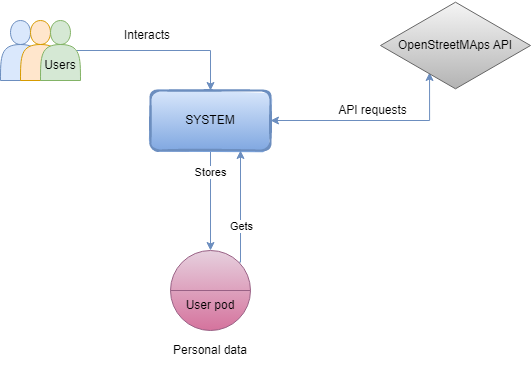
Entity |
Description |
User |
Interacts with the application front-end and sends requests to the backend. |
POD |
Stores user’s private information. In case the user is not registered it creates a new POD. |
System |
It is responsible for making the application work. |
API |
We are using OpenStreet Maps to visualize the locations. |
3.2. Technical Context
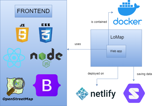
Technology |
Description |
REACT |
We use it to develop the frontend of the application |
SOLID |
We use SOLID PODs to store users information |
JavaScript |
Principal language for our code application |
CSS |
Language to set different styles and positions to our components. |
Docker |
Used for the system deployment |
Netlify |
Used for the system deployment |
Bootstrap |
Simplifies the use of CSS and HTML, using the HTLM5 standards. |
We use OpenStreet Maps as the main API for the project to visualize the maps.
4. Solution Strategy
We have chosen to use the next technologies on the app:
-
React: is a Javascript library focused on developing user interfaces so we decided to use it because of its big documentation and easy learning. It is also a solid base for creating apps with Javascript.
-
SOLID: is an acronym that refers to five good and essential principles for the design of a software architecture (Single Responsibility, Open/Closed, Liskov Substitution, Interface Segregation and Dependency Inversion). With this principles the user knows that all his "sensitive data" is safe and decentralized. We use it because it is required on the project.
-
Javascript: is an interpreted programming language based on prototypes, imperative and dynamic. We will use it on both frontend and backend.
-
CSS: is a graphic programming language oriented to define the repesentation of a document. We will use it as part of the frontend of the app.
-
Docker: is a software platform that allows to create, try and implement new apps easily and fast. We will use it for the fast deployment of our web application.
-
Netlify: is a cloud server provider which we will use to deploy our app. It is also free (for our specific case) and it’s one of the fastest options for deploying the app.
-
Github: is a version management system where all the code will be stored, structured and modified.
-
Bootstrap: is a framework that provides a collection of tools to simplify the use of html and css in the application.
4.1. Why this technologies?
-
React, CSS and Javascript were chosen to reach a good level of usability and accesibility.
-
Github was chosen for version control and organization and communication between the team.
-
Bootstrap was chosen because the facilities it provides and to have a nice, clean and responsive view to the web app.
-
Netlify was chosen because of its deployment, which it’s very easy and it automaticaly builds when updating the app.
5. Building Block View
The building block view shows the static decomposition of the system into building blocks (modules, components, subsystems, classes, interfaces, packages, libraries, frameworks, layers, partitions, tiers, functions, macros, operations, datas structures, …) as well as their dependencies (relationships, associations, …)
This view is mandatory for every architecture documentation. In analogy to a house this is the floor plan.
Maintain an overview of your source code by making its structure understandable through abstraction.
This allows you to communicate with your stakeholder on an abstract level without disclosing implementation details.
The building block view is a hierarchical collection of black boxes and white boxes (see figure below) and their descriptions.
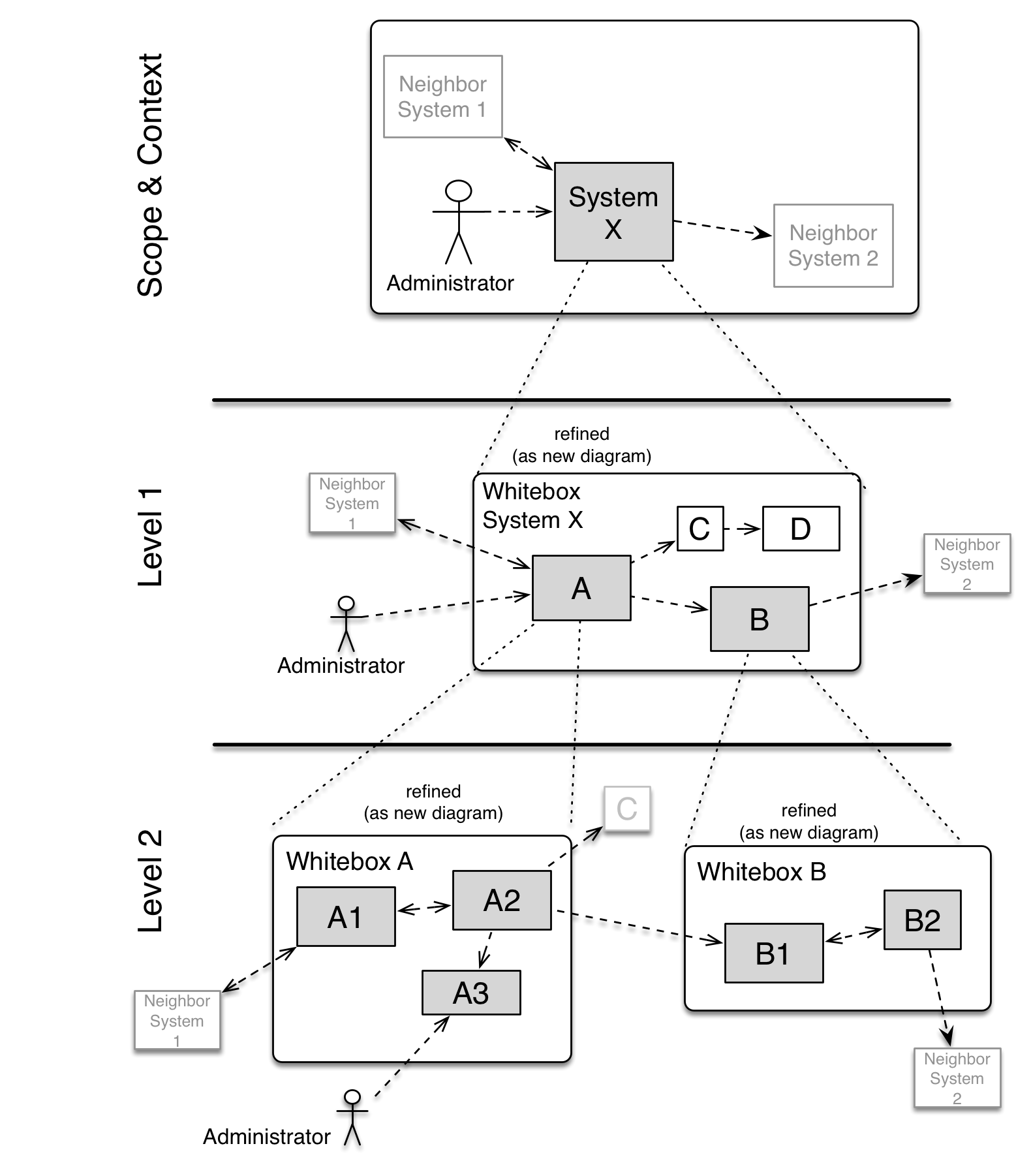
Level 1 is the white box description of the overall system together with black box descriptions of all contained building blocks.
Level 2 zooms into some building blocks of level 1. Thus it contains the white box description of selected building blocks of level 1, together with black box descriptions of their internal building blocks.
Level 3 zooms into selected building blocks of level 2, and so on.
5.1. Whitebox Overall System - Level 1
Here, the app is represented as a whitebox. Inside of it we can see the component-based architecture in black boxes:
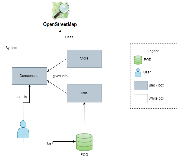
5.1.1. Black Box descriptions of Overall System
Name |
Responsability |
Utils |
Stores/gets data from personal pods, images… Gives information to the component. |
Store |
Stores/gets the context of the user to the correct functionality of the component. |
Components |
Is the final view of the application and interacts with the final user, self managed. |
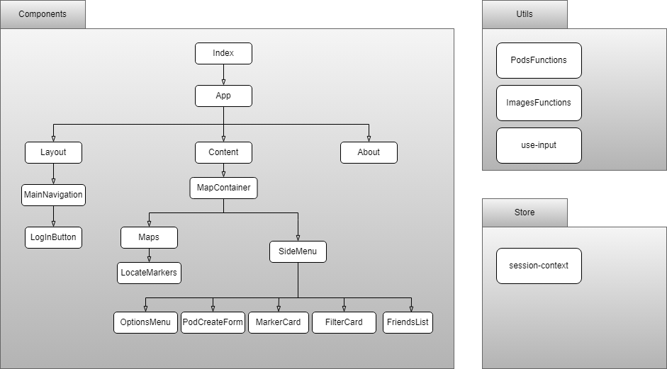
5.2. Building block view - Level 2
6. Runtime View
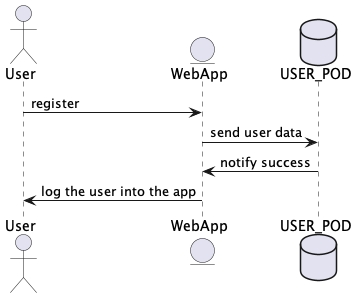
6.1. Register User
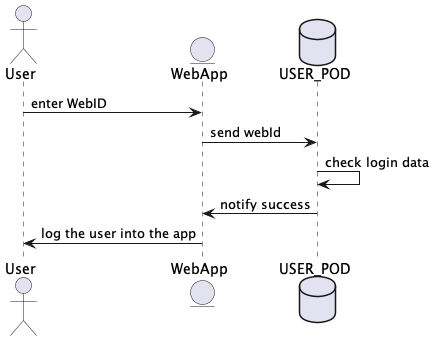
6.2. User Login Pod
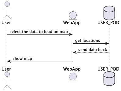
6.3. Visualize map
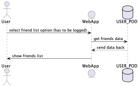
6.4. Friends list
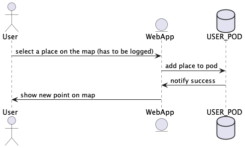
6.5. Add places to map
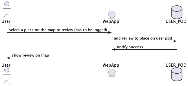
6.6. Reviews
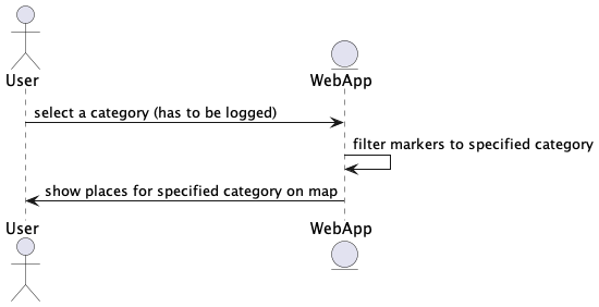
6.7. Filter map
7. Deployment View
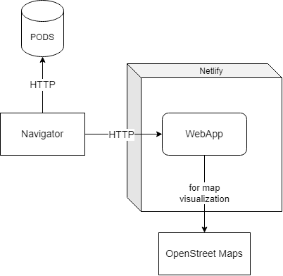
7.1. Infrastructure Level 1
- Motivation
-
This diagram helps us to visualise which components we will use and their dependencies.
- Quality and/or Performance Features
-
High performance as we operate directly.
- Mapping of Building Blocks to Infrastructure
-
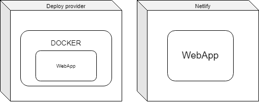
7.2. Infrastructure Level 2
- Motivation
-
This diagram allow us to have a more exhaustive vision about how the deployment on every deployment service using Docker and also the deployment on Netlify.
- Quality and/or Performance Features
-
We are going to use Netlify to deploy the application, working as a remote server. We will use Docker to in case it’s wanted to deploy on other services.
- Mapping of Building Blocks to Infrastructure
-
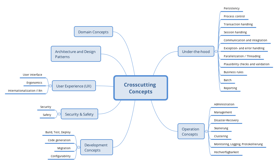
8. Cross-cutting Concepts
This section describes overall, principal regulations and solution ideas that are relevant in multiple parts (= cross-cutting) of your system. Such concepts are often related to multiple building blocks. They can include many different topics, such as
-
domain models
-
architecture patterns or design patterns
-
rules for using specific technology
-
principal, often technical decisions of overall decisions
-
implementation rules
Concepts form the basis for conceptual integrity (consistency, homogeneity) of the architecture. Thus, they are an important contribution to achieve inner qualities of your system.
Some of these concepts cannot be assigned to individual building blocks (e.g. security or safety). This is the place in the template that we provided for a cohesive specification of such concepts.
The form can be varied:
-
concept papers with any kind of structure
-
cross-cutting model excerpts or scenarios using notations of the architecture views
-
sample implementations, especially for technical concepts
-
reference to typical usage of standard frameworks (e.g. using Hibernate for object/relational mapping)
A potential (but not mandatory) structure for this section could be:
-
Domain concepts
-
User Experience concepts (UX)
-
Safety and security concepts
-
Architecture and design patterns
-
"Under-the-hood"
-
development concepts
-
operational concepts
Note: it might be difficult to assign individual concepts to one specific topic on this list.
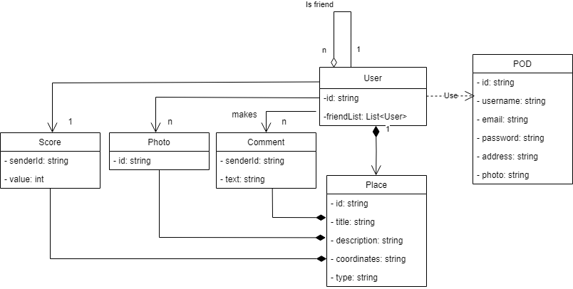
8.1. Domain model
Name |
Description |
POD |
User information. |
User |
User who uses the application. Can be friend with other users. |
Comment |
A comment made by a user related to a place. |
Score |
A score submitted by a user related to a place. |
Photo |
A photo upload by a user related to a place. |
Place |
A location in the map that is static over time. |
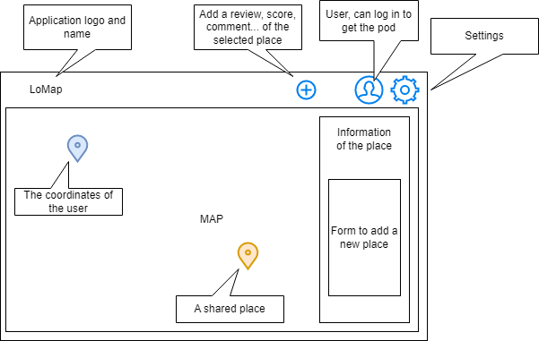
8.2. User Interface
Prototype version:
9. Design Decisions
Decision |
Details |
Advantages |
Disadvantages |
Architecture |
We will use component-based architecture (CBA) as the architecture design. |
We will have a very well structured code separarated by components. |
The separation in components makes the application complicated. |
OpenStreetMaps API |
We will use the API to create the map. |
It’s free, not like the Google Maps API. |
It’s the first time using it, we’ll have to adapt. |
Netlify |
We use them to deploy the application. |
It’s free and it provides a very fast deployment. |
The general cloud computing issues as backup protection. |
CSS+Bootstrap |
We use it to add a nice look to the application. |
It’s a well known stylesheet languaje for the team, responsive. |
Different browsers work different, we have to take care of it. |
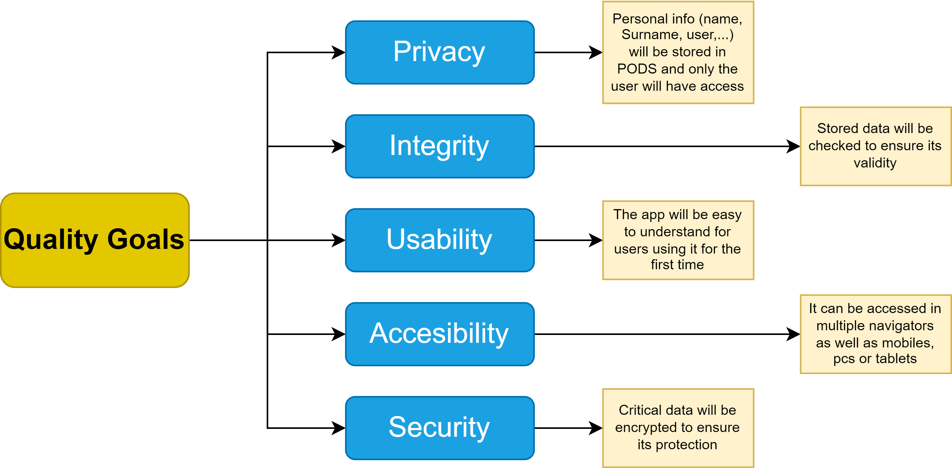
10. Quality Requirements
10.1. Quality Tree
10.2. Quality Scenarios
Quality |
Scenario |
User Priority (App success) |
Developer Priority (Difficulty to achieve) |
Privacy |
A user who wants to access their friend list. Because we are using SOLID, this information will be stored in its personal POD, only the user can access to this info. |
HIGH |
MEDIUM |
Integrity |
When an update releases, the information stored will still be there and valid. |
LOW |
HIGH |
Usability |
A user want to add a new point on the map. There will be an easy way to do it that is intuitive to users |
HIGH |
LOW |
Accesibility |
A user who want to access with their phone. The application will adapt so they can use it on multiple platforms |
HIGH |
MEDIUM |
Security |
If a user wants to make a point on the map with their current location, a message will be shown to ask for permision to use their location. |
HIGH |
HIGH |
11. Risks and Technical Debts
11.1. Risks
This is a list of identified technical risks, ordered by priority (1 is the highest priority).
-
Not knowing some of the technologies that we decided to use in this application. Such as SOLID (and PODs), REACT, AWS, OpenStreet Maps API or Docker. Some of us haven’t worked with web applications either.
-
In order to avoid this risk or minimize its damage, we will have to learn how to use this technologies, having to spend some time to do it.
-
-
Due to having other projects and exams from other subjects, we will have limited time to work on this project that can lead to errors for rushing the project.
-
In order to avoid this risk or minimize its damage, we will have to plan well how we are going to do this project.
-
-
A member of the group could leave it or drop the subject, having to work the same with less members.
-
In order to avoid this risk or minimize its damage, we will have to quickly restructure the assignments to each member so the project can continue. We must avoid the bus factor.
-
-
Some of the members of the group didn’t know each other before the project, this could lead to misunderstandings because we are not close enough to voice our concerns or ideas.
-
In order to avoid this risk or minimize its damage, we will have to be open to the other team members, always consider their ideas and help each other if someone doesn’t understand something.
-
11.2. Technical Debt
This is a list of identified technical debts, ordered by priority (1 is the highest priority).
12. Glossary
| Term | Definition |
|---|---|
API |
Application Programming Interface. It’s a set of defined rules that enable different applications to communicate with each other. It acts as an intermediary layer. |
Backend |
Part of a computer application or a program’s code that allow it to operate and that cannot be accessed by a user |
Decentrilized/centrilized Data |
In a centralized network, all users are connected to a central server that stores complete network data and user information. On the contrary, a decentralized network has several peer-to-peer user groups wherein each group has its separate server that stores data and information relevant to only that particular group. |
Deployment |
Mechanism through which applications, modules, updates, and patches are delivered from developers to users |
Framework |
Tool that provides ready-made components or solutions that are customized in order to speed up development |
Frontend |
Part of computer programming that focuses on the coding and creation of elements and features that will then be seen by the user. |
GitHub |
Code hosting platform for version control and collaboration. |
Component-based Architecture |
Process of building software based on reusable components. Structure of components that contains other smaller components. |
POD |
Pods are like secure personal web servers for data. When data is stored in someone’s Pod, they control which people and applications can access it. |
SOLID |
SOLID is an acronym for the first five object-oriented design principleS. These principles establish practices that lend to developing software with considerations for maintaining and extending as the project grows. |
Bootstrap |
A multiplatform library, open source toolbox to design web applications. |
Netlify |
A remote cloud computing company that offers a development platform that provides: serverless backend services, build and deployment functionality for dynamic websites and web applications. |
13. Test
In this section we are going to test the application. We will use the following technologies for testing:
| Name | Description |
|---|---|
Sonarcloud |
Checks the code coverage and quality for the application tests. |
Cucumber |
Technology used for behavior driven development (BDD) to write acceptance tests for the application. |
Gatling |
Technology used for load testing the application. |
We are going to analyze the results of the Gatling tests in the following section.
13.1. Sonarcloud
Sonarcloud allows us to check the code coverage and quality of the application. The following image shows the results of the Sonarcloud tests:
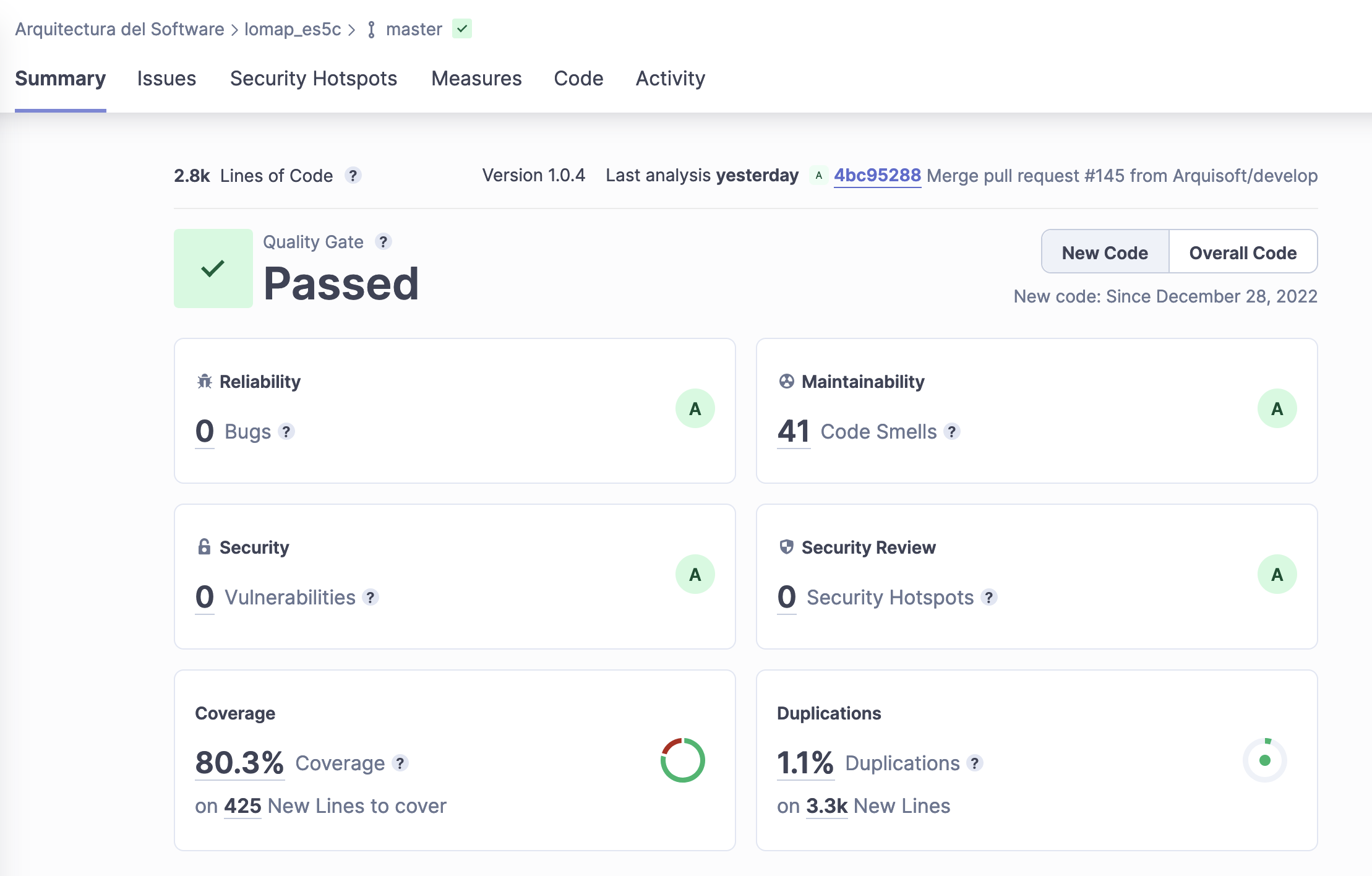
We can see how we have a 80% of code coverage for the application. We can also see that the code quality is good, with 0 bugs and 0 security vulnerabilities. We can also see that the code duplication is 1.1% which seems to be a good value thinking that the application hasn’t been developed by a single person and a refactor of the code has never been done.
13.2. Gatling
After running the Gatling tests, we can analyze the results. After analyzing the results, we can see that the application at 100 active users and 50 requests per second has a response time of 0.8 seconds for a 40% of success rate. The following image shows the results of the Gatling tests:
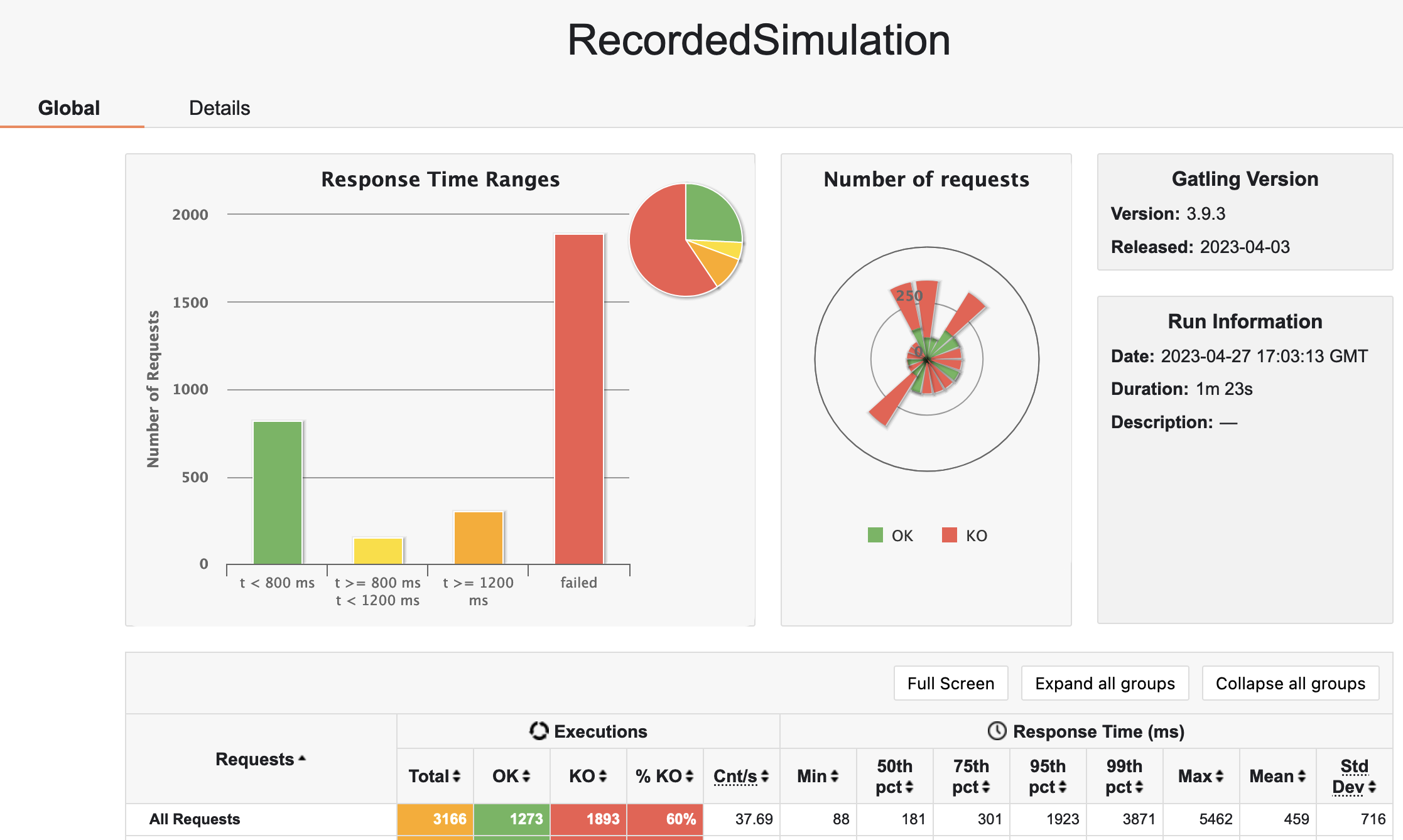
Maybe the success rate is not the best, but we can see that the response time is very good. We have to take into account that the application is running in a free instance of Netlify, so the performance is not the best. If we want to improve the performance, we can migrate the application to another cloud provider, like AWS, Azure or Google Cloud. We also need to take into account that the test have been run
when a lot of traffic has been generated to Inrupt POD provider. This can affect the results of the tests.
13.3. Usability
In this section we are going to have a look at the usability of the application. We have done a usability test with 5 users. The following table shows the results of the usability test:
| Question | Luis | Carmen | Paula | Ana | David | Average |
|---|---|---|---|---|---|---|
Is the application intuitive? |
10 |
10 |
9 |
8 |
7 |
8.8 |
Is the application easy to use? |
10 |
10 |
8 |
9 |
7 |
8.8 |
Is the application attractive? |
8 |
9 |
10 |
10 |
9 |
9.2 |
Is the application fast? |
7 |
6 |
7 |
8 |
8 |
7.2 |
Is the application accessible? |
9 |
9 |
9 |
9 |
8 |
8.8 |
Is the application useful? |
10 |
10 |
8 |
9 |
9 |
9.2 |
How would you rate the application? |
9 |
10 |
10 |
10 |
10 |
9.8 |
We can see that overall the application has a good user rate. The users have rated the application with a 9.8 out of 10. The users have also rated the application as intuitive, easy to use, attractive, accessible and useful. The only thing that the users have not rated very well is the speed of the application. The found themselves waiting for the application to load some times.
The users have the following age: * Luis: 60 * Carmen: 55 * Paula: 19 * Ana: 66 * David: 22
We can see that the users are from different ages, so we can say that the application is suitable for all ages.
About arc42
arc42, the Template for documentation of software and system architecture.
By Dr. Gernot Starke, Dr. Peter Hruschka and contributors.
Template Revision: 7.0 EN (based on asciidoc), January 2017
© We acknowledge that this document uses material from the arc 42 architecture template, http://www.arc42.de. Created by Dr. Peter Hruschka & Dr. Gernot Starke.