
1. Introducción y objetivos
1.1. Descripción de los requisitos
En la aplicacion web los usuarios podran añadir lugares de distintas categorias (tiendas, bares, restaurantes, monumentos…). Tambien podran mostrar lugares en un formato tipo mapa, ademas de asociar puntuaciones, comentarios, etc. sobre los mismos.
Se hara uso de SOLID para almacenar los lugares de los usuarios (cada usuario tendra su propio POD), y estos mismos decidiran quien puede tener acceso a esos datos.
El sistema permitira mostrar lugares e informacion tomada de sus amigos, y se podra aplicar filtros (por categoria, amigos, etc.) a los resultados para obtener datos mas especificos
1.2. Objetivos de calidad
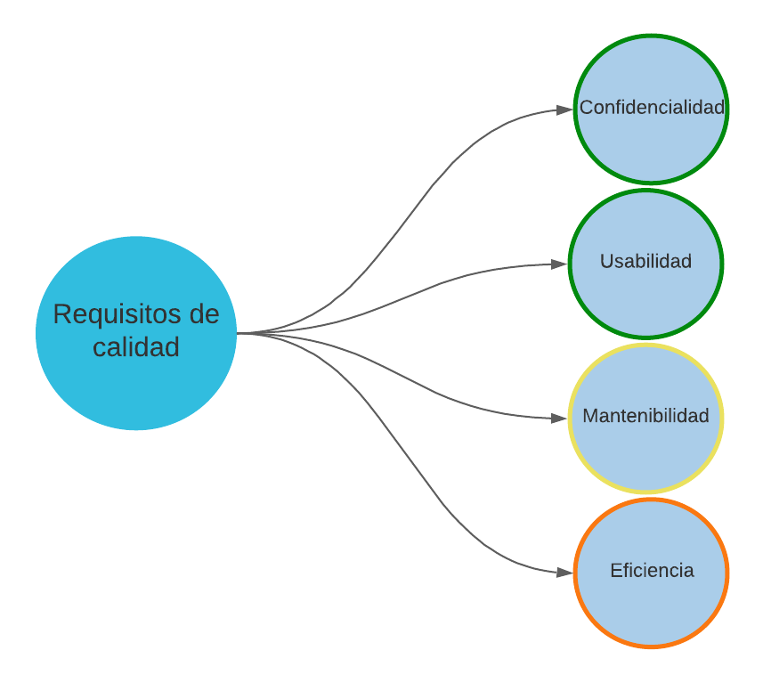
Los principales atributos de calidad para este proyecto son los siguientes:
| Objetivo | Detalles |
|---|---|
Confidencialidad |
Uno de los objetivos principales del sistema será mantener la privacidad del usuario. De forma que, con la utilización de SOLID, de la información almacenada solo se mostrarán los datos primordiales para garantizar el correcto funcionamiento del sistema y/o la que haya sido autorizados por el propio usuario. |
Usabilidad |
El usuario deberá poder utilizar el sistema de una forma sencilla e intuitiva, de forma que se proporcione una buena experiencia. |
Mantenibilidad |
El sistema deberá poder ser actualizado (con nuevos añadidos o modificaciones) de forma que estos cambios provoquen el menor número de cambios posibles. |
Eficiencia |
El sistema deberá proporcionar al usuario una buena experiencia dentro de lo posible con las tecnologías usadas, por ejemplo no teniendo que espera mucho tiempo para ver el resultado de una operación. |
1.3. Stakeholders
| Role/Name | Contact | Expectations |
|---|---|---|
Coordinadores del proyecto |
Profesores de la asignatura |
Aplicación SOLID funcional con los requisitos indicados en el enunciado y que demuestre los conocimientos adquiridos de la asignatura. |
Cliente |
Ayuntamiento de Bruselas |
Aplicación de mapas para los ciudadanos. |
Usuarios |
Ciudadanos de Bruselas |
Aplicación intuitiva que satisfaga sus necesidades como usuarios (crear mapas personalizados con puntos de interés) |
Administrador |
Equipo de desarrollo |
Usuario con privilegios que tiene acceso a datos y funcionalidad especial de la aplicación |
2. Restricciones Arquitectónicas
2.1. Restricciones técnicas
| Restricción | Descripción |
|---|---|
SOLID Pods |
Los Pods de SOLID nos permitirán almacenar de forma segura los datos de los usuarios |
Git |
Utilizaremos los repositorios de GitHub para subir el código de la aplicación. |
React |
Para la creación del Frontend de la aplicación utilizaremos la biblioteca de JavaScript React |
JavaScript |
Utilizaremos JavaScript como lenguaje de programación para la aplicación, la razón principal es que todos nos encontramos más cómodos utilizándolo. |
2.2. Restricciones de negocio
| Restricción | Descripción |
|---|---|
Equipo |
El equipo está formado por 4 personas, las cuales no nos conocemos y esto al principio puede provocar retrasos en el proyecto. |
Tiempo |
Los miembros del equipo tenemos más asignaturas con las que debemos cumplir, además de otras obligaciones que nos pueden obstaculizar a la hora de realizar el trabajo. |
Nuevos conceptos |
Debemos aprender por nuestra cuenta a utilizar nuevas tecnologías. |
2.3. Convenio
| Restricción | Descripción |
|---|---|
SOLID |
La aplicación seguirá los principios SOLID para mantener la privacidad del usuario |
Documentación |
La documentación seguirá la arquitectuar arc42 |
Idioma |
La documentación se realizará en español, al ser nuestro idioma nativo |
3. Alcance y contexto del sistema
3.1. Contexto de negocio
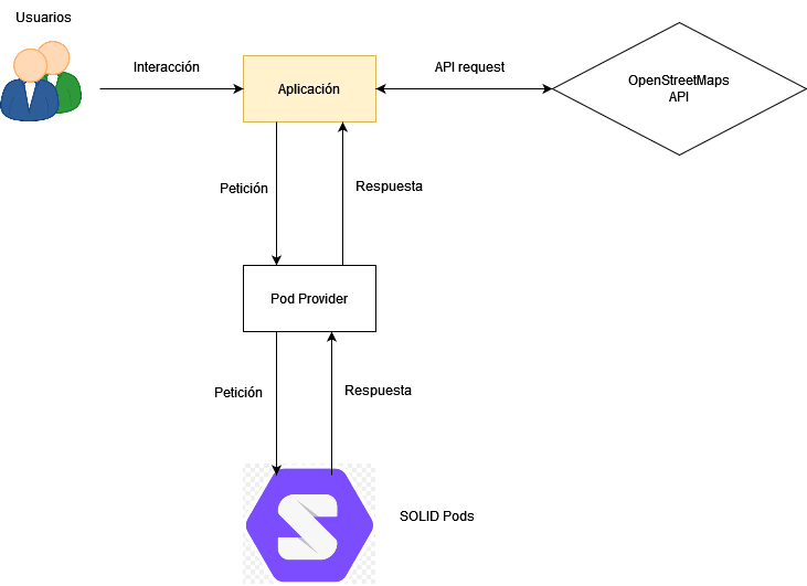
| Elemento de comunicación | Entrada | Salida |
|---|---|---|
Usuario |
El usuario recibirá una respuesta de la aplicación a través del dispositivo que esté utilizando para acceder a la web |
Será el propio usuario el que interactuará con la aplicación |
Solid POD |
El Pod será creado por el usuario para poder almacenar la información necesaria |
La información solo se mostrará si el usuario es autentificado |
OpenStreetMap Maps API |
La API obtendrá las diferentes ubicaciones del mapa |
Nos mostrará información acerca de los lugares (comentarios, fotos, reseñas …) |
3.2. Contexto Técnico
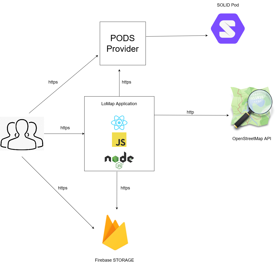
| Tecnología utilizada | Descripción |
|---|---|
SOLID |
Nos permitirá almacenar de forma segura la información del usuario |
JavaScript |
Lenguaje de programación que utlizaremos durante el desarrollo |
React |
Biblioteca de JavaScript que se utilizará a la hora de crear las interfaces de nuestra aplicación |
Firebase |
Plataforma móvil de Google que hemos utilizado para almacenar las imagénes de los usuarios |
OpenStreetMap Maps API |
Con la API obtendremos las funciones del mapa |
4. Solution Strategy
Decisiones fundamentales que se han tomado para llevar a cabo el trabajo de la mejor forma posible.
4.1. Decisiones tecnológicas
Se han decidido las siguientes tecnologías para llevar a cabo el desarrollo de la aplicación:
-
React: biblioteca de código abierto de JavaScript diseñada para crear interfaces de usuario.
-
GitHub: para llevar un control de versiones
-
Solid: una aplicación SOLID asegura la privacidad de los datos de sus usuarios.
-
MVC: patrón arquitectónico ideal para aplicacioens con interfaz de usuario.
-
JavaScript: lenguaje de programación basado en JavaScript que añade tipos estáticos y objetos basados en clases.
-
Tailwind UI: es el frameworks de CSS que vamos a utilizar en la aplicación.
-
OpenStreetMap: la API elegida para implementar la funcionalidad principal de la aplicación: un mapa.
4.2. Objetivos de calidad
Algunos objetivos de calidad claves y cómo lograrlos:
Gracias a los pods que nos proporciona SOLID, los usuarios podrán guardar sus datos de forma segura con la garantía de que estos no puedan ser accedidos por terceros sin su previa autorización.
Se quiere lograr una aplicación que sea fácil de usar para sus clientes. Gracias a React la aplicación contará con una interfaz gráfica intuitiva que haga pensar lo menos posible al usuario.
El equipo de desarrollo de la aplicación responderá a las necesidades del usuario en todo momento, actualizando la aplicación con nueva funcionalidad o solucionando errores.
4.3. Decisiones organizativas
Medios que se han usado para facilitar una buena organización del trabajo:
-
Uso de ramas: para dividir los distintos flujos de trabajo. La versión comercial de la aplicación figura en la rama master, mientras que en la develop se añadirán los futuros cambios para comprobar que la aplicación funciona antes de pasarlos a la rama master. Se usarán tantas ramas como sea necesario.
-
Issues: donde figuran las actas de las reuniones del equipo de desarrollo.
-
Tableros del proyecto: forma de organizar las distintas tareas a realizar, tanto de implementación, como investigación, documentación, etc. Las tareas se irán moviendo al bloque correspondiente según avance su progreso, y todos los miembros del equipo podrán ver el progreso general de la aplicación.
5. Vista del Bloque de Construccion
The building block view shows the static decomposition of the system into building blocks (modules, components, subsystems, classes, interfaces, packages, libraries, frameworks, layers, partitions, tiers, functions, macros, operations, datas structures, …) as well as their dependencies (relationships, associations, …)
This view is mandatory for every architecture documentation. In analogy to a house this is the floor plan.
Maintain an overview of your source code by making its structure understandable through abstraction.
This allows you to communicate with your stakeholder on an abstract level without disclosing implementation details.
The building block view is a hierarchical collection of black boxes and white boxes (see figure below) and their descriptions.
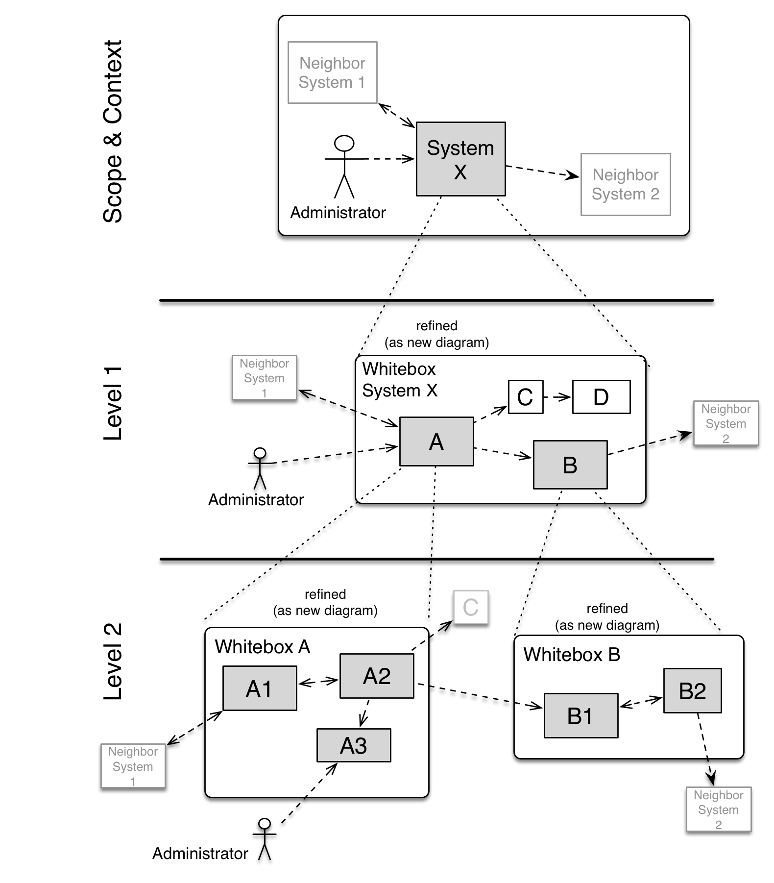
Level 1 is the white box description of the overall system together with black box descriptions of all contained building blocks.
Level 2 zooms into some building blocks of level 1. Thus it contains the white box description of selected building blocks of level 1, together with black box descriptions of their internal building blocks.
Level 3 zooms into selected building blocks of level 2, and so on.
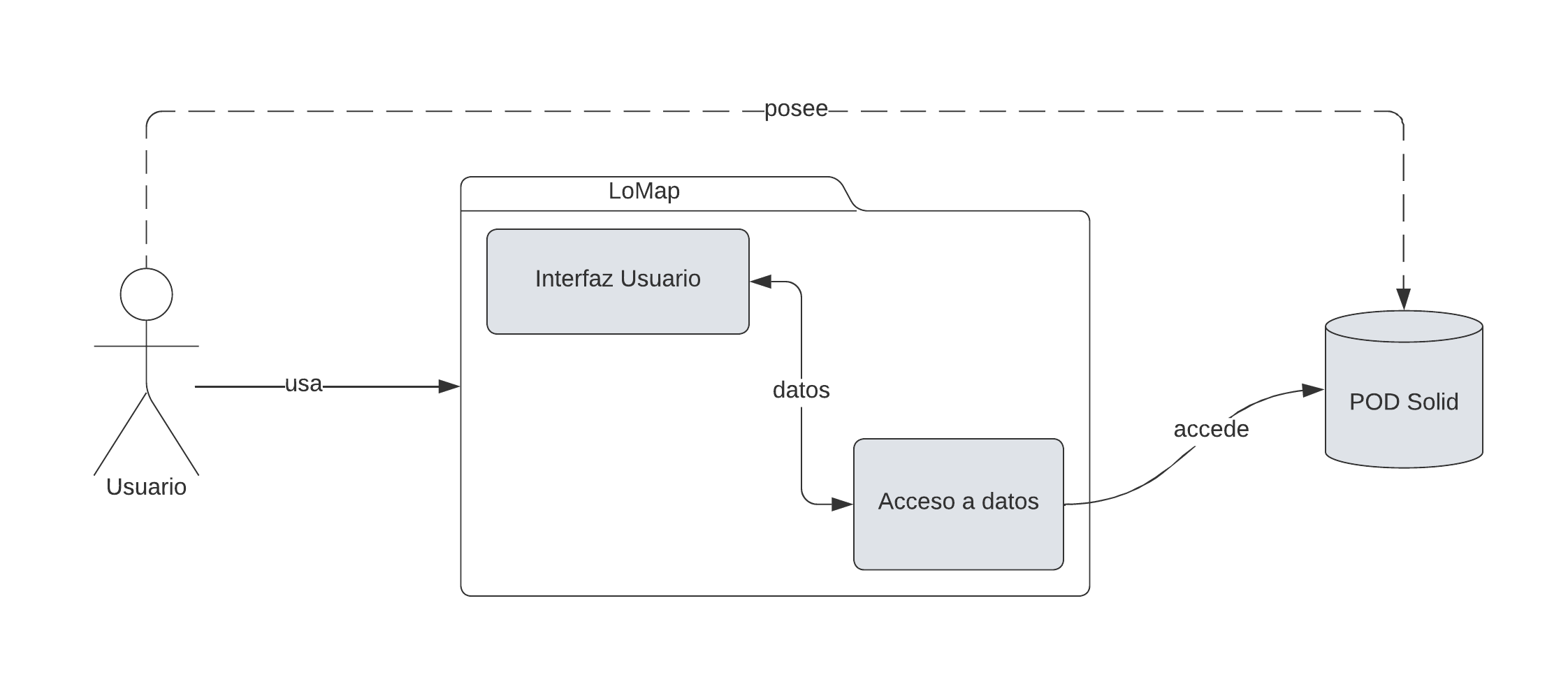
5.1. Caja Blanca General del Sistema
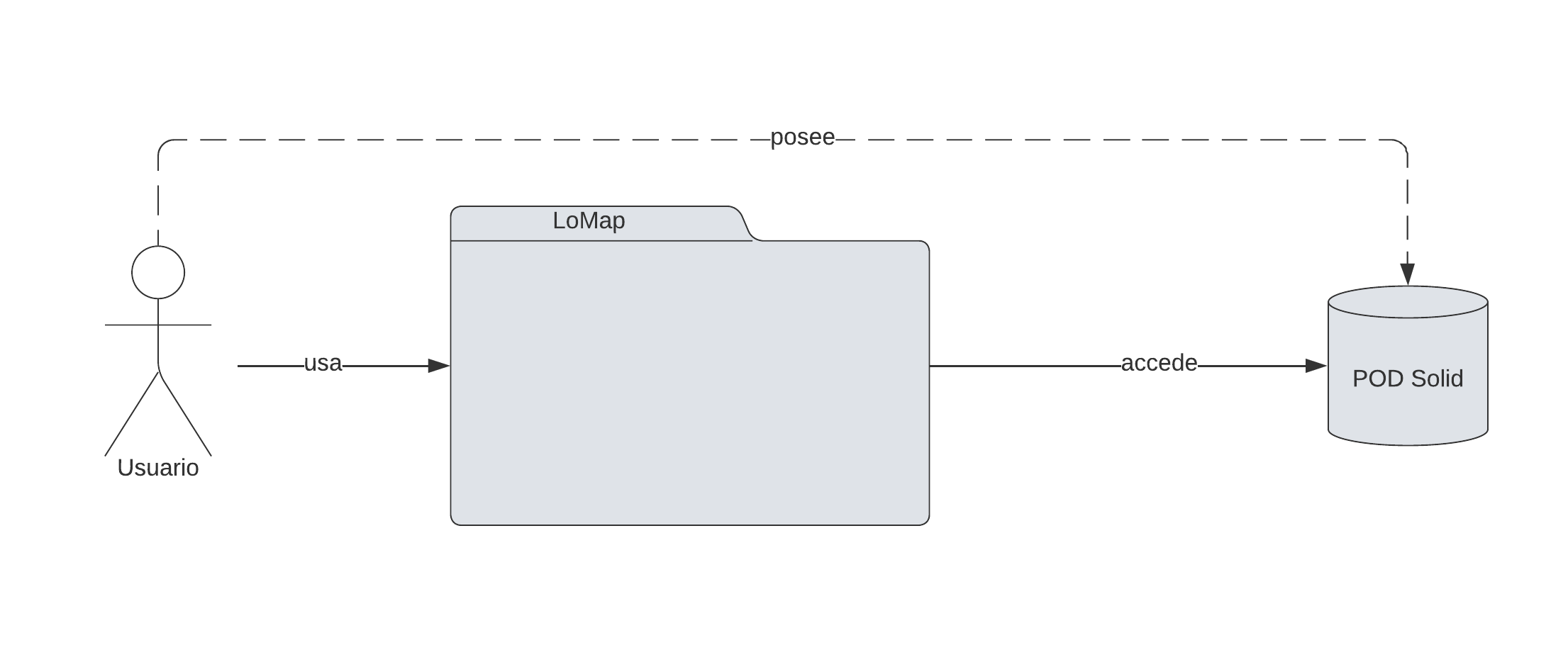
- Motivacion
-
En este diagrama podemos observar los principales agentes de la aplicación (los cuales se verán en detalle más adelante).
| Nombre | Responsabilidad |
|---|---|
LoMap |
es la aplicación en si, en ella están contenidas todas las funcionalidades y servicios necesarios |
PODS |
es donde se almacenan los datos de los usuarios. |
5.2. Nivel 2
Aqui se mostrarán las dos partes principales que componen la aplicación.
Nombre |
Responsabilidad |
Interfaz de usuario |
Contiene las interfaces y vistas que se le mostrarán al usuario |
Acceso a datos |
Parte de la aplicación que se ocupara del intercambio de datos entre la interfaz de usuario y los servicios usados (POD Solid y Firebase) |
5.3. Nivel 3
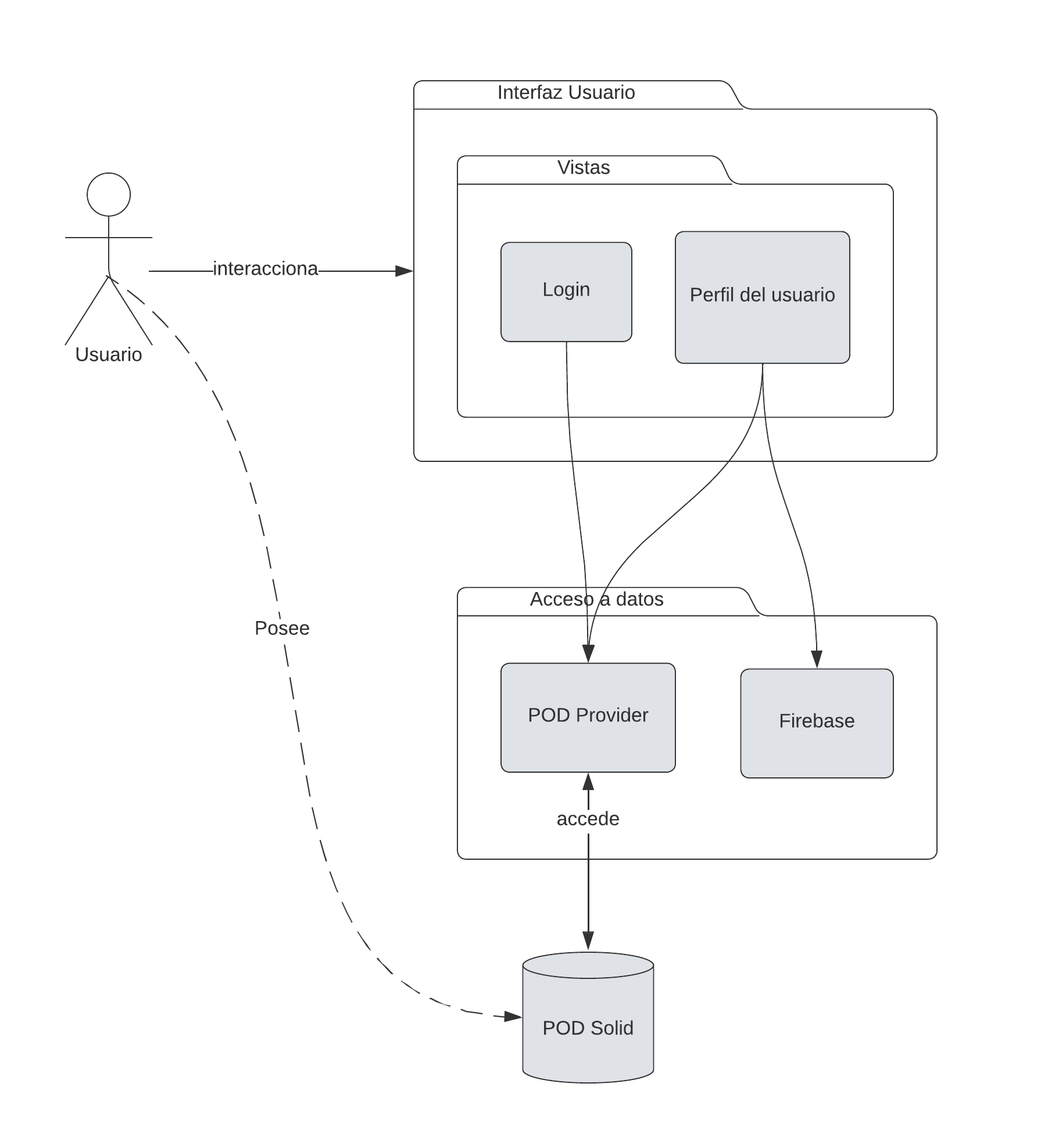
- Motivacion
-
Estructura detallada del sistema.
- Bloques de construcción contenidos
| Nombre | Descripcion |
|---|---|
Vistas |
Parte de la aplicacion con la cual el usuario interacciona directamente. |
Login |
Pantalla inicial de la aplicacion. Se muestra un mensaje con el nombre de la misma y una pequeña descripcion, ademas del boton de login para entrar en la cuenta personal. |
Perfil del usuario |
Vista mas importante de la aplicacion. Aqui se encuentra practicamente toda la funcionalidad de la misma, desde ver tus propios mapas y los de tus amigos, a crear nuevos mapas y puntos, añadir nuevos amigos, etc. |
Firebase |
Usada para poder guardar y acceder a las imagenes que los usuarios añaden a la descricion de los puntos. |
6. Vista en Tiempo de Ejecución
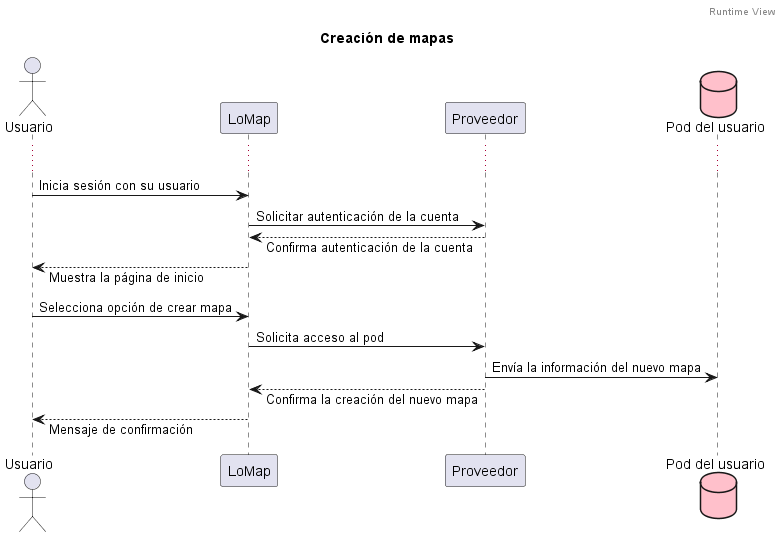
6.1. Usuario crea un mapa nuevo
El usuario selecciona la opción de crear un mapa nuevo, es decir, aún no tiene puntos de interés.
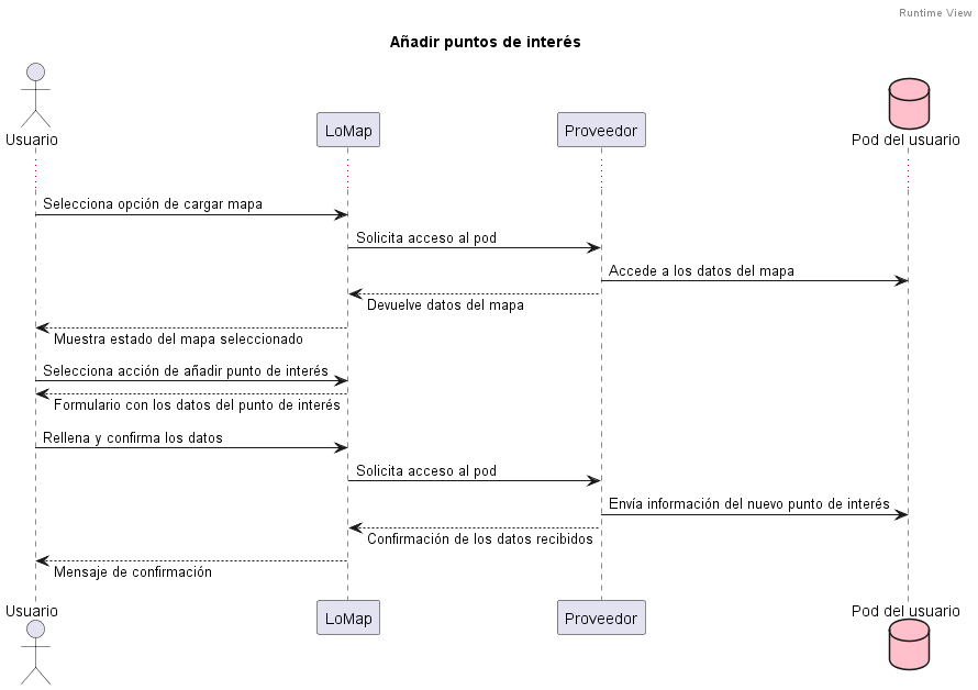
6.2. Usuario añade un restaurante a su mapa
El usuario añade a uno de sus mapas un restaurante como punto de interés.
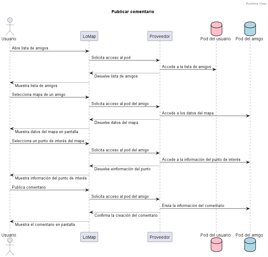
6.3. Usuario publica un comentario
El usuario accede a uno de los mapas públicos de uno de sus amigos y deja un comentario en un punto de interés.
7. Vista de Despliegue
7.1. Nivel de Infraestructura 1
- Mapeo de Elementos de la Infraestructura
| Bloque | Descripcion |
|---|---|
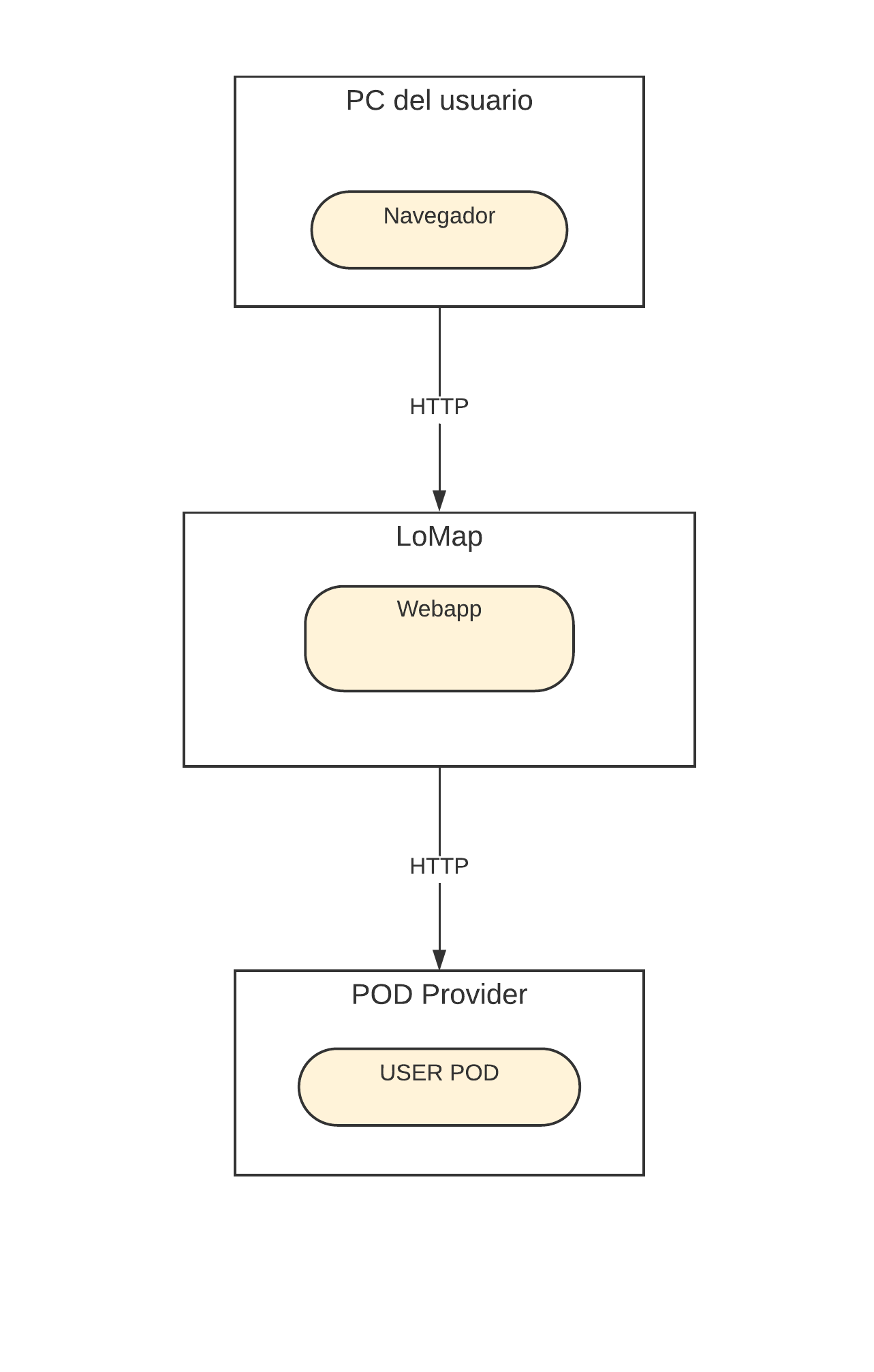
Browser |
Mediante este, el usuario utilizara la aplicacion |
Webapp |
La capa que contendra las vistas que se mostraran a los usuarios |
USER POD |
Donde se guardaran los datos personales de los usuarios (un POD por usuario) |
Firebase |
Donde se guardarán y cargarán las imágenes subidas por los usuarios |
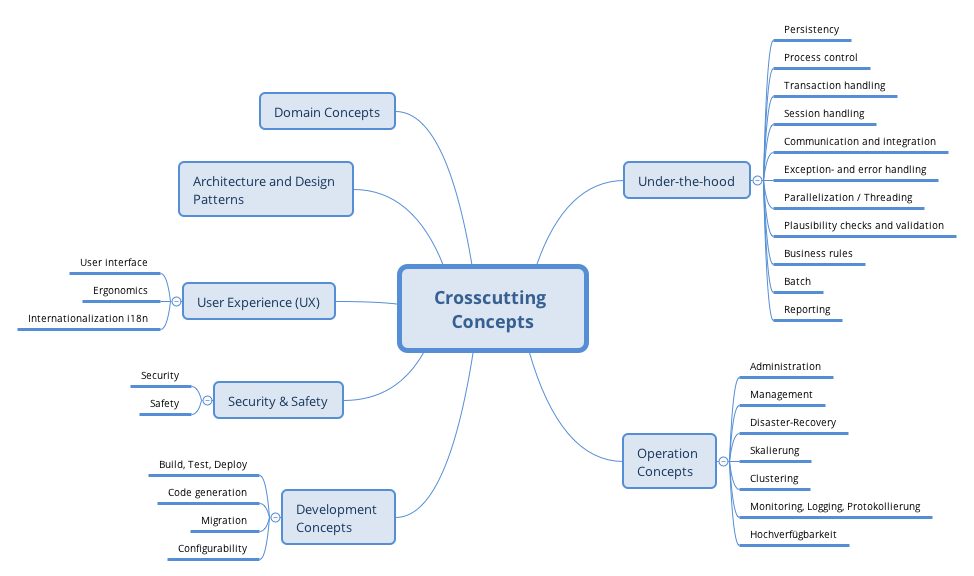
8. Conceptos transversales
This section describes overall, principal regulations and solution ideas that are relevant in multiple parts (= cross-cutting) of your system. Such concepts are often related to multiple building blocks. They can include many different topics, such as
-
domain models
-
architecture patterns or design patterns
-
rules for using specific technology
-
principal, often technical decisions of overall decisions
-
implementation rules
Concepts form the basis for conceptual integrity (consistency, homogeneity) of the architecture. Thus, they are an important contribution to achieve inner qualities of your system.
Some of these concepts cannot be assigned to individual building blocks (e.g. security or safety). This is the place in the template that we provided for a cohesive specification of such concepts.
The form can be varied:
-
concept papers with any kind of structure
-
cross-cutting model excerpts or scenarios using notations of the architecture views
-
sample implementations, especially for technical concepts
-
reference to typical usage of standard frameworks (e.g. using Hibernate for object/relational mapping)
A potential (but not mandatory) structure for this section could be:
-
Domain concepts
-
User Experience concepts (UX)
-
Safety and security concepts
-
Architecture and design patterns
-
"Under-the-hood"
-
development concepts
-
operational concepts
Note: it might be difficult to assign individual concepts to one specific topic on this list.
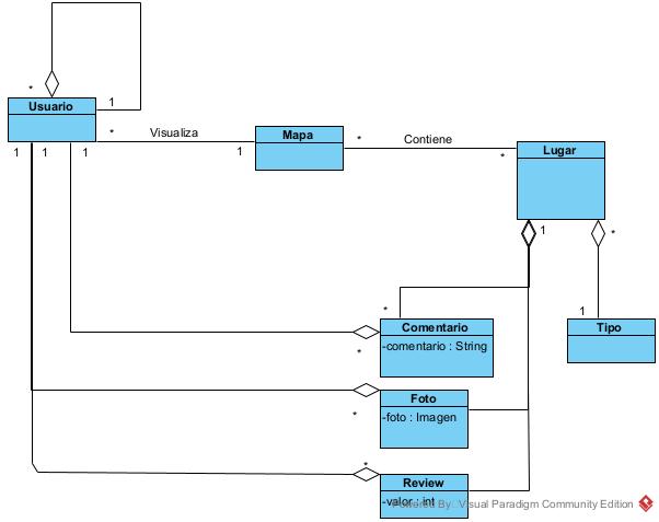
8.1. Modelo de dominio
9. Descisiones de diseño
9.1. Decisiones de diseño
| Decisión | Ventaja | Desventaja |
|---|---|---|
React JS |
Fácil de aprender, flexible y de código abierto |
Falta de documentación oficial y se deben tomar decisiones al no haber un patrón de diseño |
Español como Idioma |
Al ser nuestra lengua nativa no es mucho mas cómodo y sencillo |
Menos internacional |
OpenStreetMap API |
Fácil de usar, gratuita y ofrece diferentes opciones que pueden resultar útiles |
En ocasiones es un poco impreciso |
SOLID |
Nos va a permitir almacenar de forma segura la información del usuario |
Ninguno de nosotros a trabajo anteriormente con ellos y nos puede dificultar el trabajo |
10. Requisitos de calidad
10.1. Árbol de calidad
10.2. Escenarios de calidad
Los objetivos de calidad anteriormente mencionados en el apartado 1.2, añadiendo alguno nuevo de menor prioridad.
| Atributo de calidad | Escenario de calidad | Prioridad |
|---|---|---|
Confidencialidad |
El usuario guarda puntos de interés en su mapa. Estos solo podrán ser accedidos a sus amigos agregados en la aplicación. |
Alta |
Usabilidad |
El usuario quiere hacer uso de algunas de las funciones de la aplicación. Gracias a una interfaz intuitiva no le requiere un gran esfuerzo encontrar los componentes donde llevar a cabo las acciones y cómo realizarlas. |
Alta |
Mantenibilidad |
Un miembro del equipo de desarrollo puede integrar nueva funcionalidad a la aplicación de forma sencilla y sin tener que realizar grandes cambios en la misma. |
Media-alta |
Eficiencia |
El usuario se logea para acceder a su mapa. La página no debería tardar más de 3 segundos en mostrarlo en pantalla. |
Media-baja |
11. Riesgos y Deuda Técnica
Riesgo |
Descripción |
Trabajar con React |
No hemos trabajado con el framework y va a ser muy necesario estar informándonos constantemente |
JavaScript |
Aunque hayamos trabajado con ella anteriormente, no lo hemos hecho con mucha profundidad y aún tenemos que mejorar y aprender más. |
Uso de SOLID y sus Pods |
Es una tecnología que desconocemos por completo y deberemos aprender |
Miembros del equipo desconocidos |
Contamos con 4 miembros en el equipo, no nos concemos entre nosotros y deberemos mantener una buena comunicación |
Tiempo |
Obviamente tenemos el tiempo reducido, además de que todos tenemos más asignaturas a las que debemos también darle nuestro tiempo |
12. Desplegado
En nuestro caso, optamos por desplegar usando Netlify por las siguientes razones:
-
Es más fácil de usar que las otras alternativas
-
Es más rápido que las otras alternativas
-
Es completamente gratuito para webs pequeñas, a diferencia de AWS o Azure.
-
Puede vincularse directamente con github, en vez de
13. Testing
Tests e2e
4 tests
-
Login
-
Login incorrecto
-
Añadir punto
-
Eliminar punto
Todos los tests han resultado en pruebas exitosas.
Tests unitarios
-
En estos tests, buscamos comprobar el correcto funcionamiento de la aplicación.
-
Para ello, hemos ejecutado 38 tests en total, divididos en 20 suites, una por componente de la aplicación.
-
Sin embargo, debido a una serie de errores que causan que los tests se ejecuten y pasen correctamente en local, pero a la hora de ser ejecutados en GitHub Actions no funcionen y lancen excepciones, hemos tomado la decisión de excluir ciertos tests, los que acceden al Pod y hacen uso de la sesión , para el cálculo del Coverage, decisión respaldada por el profesorado.
-
También hemos de aclarar que algunos de esos tests se encuentran comentados para evitar problemas.
Tests de carga
-
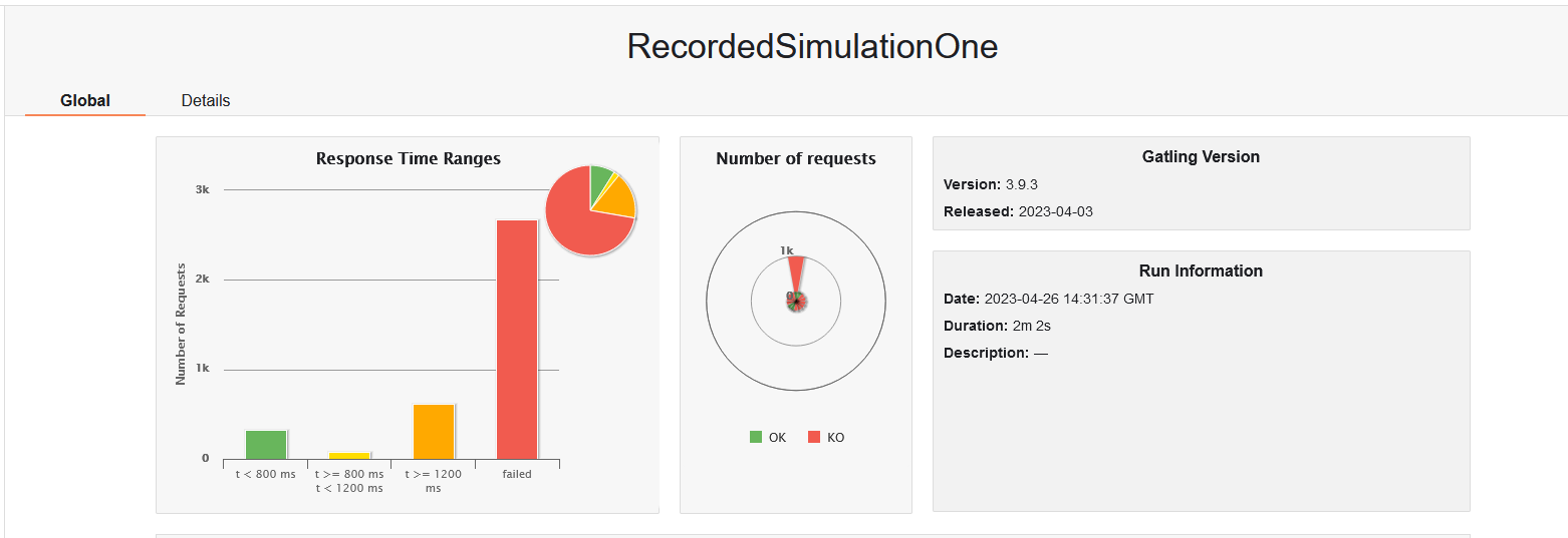
Para estos tests hemos usado la herramienta Gatling y hemos planteado los siguientes casos:
1.Añadir un punto (1000 usuarios por minuto)
Consiste en realizar las operaciones de adición de un punto 1000 veces por minuto
RESULTADOS:
    1. 323 peticiones tardaron menos de 800ms
    2. 74 peticiones tardaron entre 800 y 1200
    3. 614 peticiones tardaron más de 1200 ms
    4. 2680 peticiones fallaron
Un 79% de las peticiones fallaron justo al iniciar sesión, cosa probablemente atribuible a problemas en los servidores de inrupt
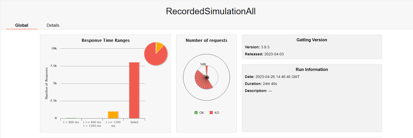
2.Escenario completo (5000 usuarios en 15 minutos)
    Consiste en realizar todas las operaciones posibles en la aplicación 5000 veces por minuto
    RESULTADOS:
        1. 92 peticiones tardaron menos de 800ms
        2. Ninguna petición tardó entre 800 y 1200
        3. 1001 peticiones tardaron más de 1200 ms
        4. 8050 peticiones fallaron
    Un 84% de las peticiones fallaron justo al iniciar sesión, cosa probablemente atribuible a problemas en los servidores de inrupt
14. Glossary
| Término | Definición |
|---|---|
React |
libreria JavaScript de codigo abierto para diseñar interfaces de usuario |
Arc42 |
Arc42 es una plantilla para la documentacion arquitectonica. |
API |
Application Programming Interface, permite la comunicación entre dos aplicaciones de software a través de un conjunto de reglas |
Solid POD |
Permite a los usuarios guardar sus datos de manera segura y descentralizada. |
JavaScript |
JavaScript es un lenguake de programacion desarrollado y mantenido por Microsoft. |
About arc42
arc42, the Template for documentation of software and system architecture.
By Dr. Gernot Starke, Dr. Peter Hruschka and contributors.
Template Revision: 7.0 EN (based on asciidoc), January 2017
© We acknowledge that this document uses material from the arc 42 architecture template, http://www.arc42.de. Created by Dr. Peter Hruschka & Dr. Gernot Starke.