1. Introduction and Goals
This is the documentation of LoMap, an application requested from the Council of Brussels to the software development company HappySw. With this application citizens will be able to have custom maps with businesses and places of their city.
1.1. Requirements Overview
-
Users can add locations in different categories.
-
Users will be able to show the locations in a map window.
-
Users can add review scores, comments, pictures, etc. about the added places.
-
Users will be able to manage which of their information is available.
-
Users information about a place will be stored in that user’s pod.
-
Users will be able to see their friends places and information about those places.
-
Users will be able to filter their maps by category, friends, etc.
1.2. Quality Goals
| Quality Goal | Description |
|---|---|
Privacy |
Each user has to be able to decide if he wants to share information. |
Decentralization |
As much information as possible should be stored in user’s pods. |
Usability |
Application must be usable by any user, whether that is a technical or non technical user. |
1.3. Stakeholders
| Role/Name | Contact | Expectations |
|---|---|---|
Interested Companies |
<Inrupt, Empathy> |
See how well the students perform around the SOLID principles for their contest |
Users |
<Citizens> |
Be able to use an easy to understand and fast aplication where they can have custom maps |
Employer |
<Council of Brussels> |
Meet the needs of citizens, whatever those are |
HappySw Owner/Professors |
<Jose Emilio Labra> |
Have his development team create a good application that can guarantee him good reputation |
HappySw Developers/Students |
<Miguel Suárez, Damián Fernández, Rubén Caño, David González> |
Desarrollar la aplicacióin según la arquitectura diseñada |
2. Architecture Constraints
2.1. Technical Constraints
| Constraint | Motivation |
|---|---|
SOLID |
Used to store the personalized maps and information in personal pods that the user provides. Also, to decentralize the personal data of the users. |
Map Genericity |
The implementation of the maps must be generic, the main implementation is for an specific place, but you can use the application where you want. |
Version Control |
We will use a public repository in GitHub with different branches. The master branch is where the final application will be. In the develop branch we will have an usable application but not a finish version. All the other branches are used to individual work. |
2.2. Organizational Constraints
| Constraint | Motivation |
|---|---|
Time |
We have some deadlines that we have to stick to. The final project must be complete before the end of April. |
Size of the team |
The team is made out of four people, we all have other projects and assignments so sometimes it could be difficult to meet or have a lot of time for the project. |
Experience |
None of us has any experience in any of the technology we are going to use. |
2.3. Conventions
| Constraint | Motivation |
|---|---|
Language |
The language of the entire documentation will be in English. |
Documentation |
The documentation is going to follow the Arc32 structure. |
3. System Scope and Context
3.1. Business Context
| Name | Inputs | Outputs |
|---|---|---|
User |
The information displayed by the webapp |
Actions to customize their map, modify content and engage with friends |
Pod provider |
Requests to retrieve information contained in a specific pod |
The requested data |
Database |
Query requests |
The result of said requests |
Map API |
Request to obtain a map view in a certain location |
The necessary to properly show the map |
3.2. Technical Context
| Interface | Explanation |
|---|---|
React |
Library to build the front-end user interface |
NodeJS |
Environment to support the backend system |
Docker |
Allows for deployment of the system |
4. Solution Strategy
4.1. Technological Decisions
For the development of the application we have decided to use JavaScript as the main language in contrast to TypeScript. This decision is based on the ease of JavaScript and also on the experience we have with it. Although TypeScript is similar to JavaScript, we decided it’s better to stick with something we now know how to use and not try to understand another new technology. In addition to JavaScript we are going to use other technologies:
-
SOLID: Solid is perfect for the development of this application, since it allows users to maintain the user’s privacy by storing information in their personal pods
-
React.js: We chose React for its simplicity, ease of learning, and reliability (as it is a widely used library in the industry, it is highly error-tested).
4.2. Top-Level Decomposition
-
Editor: For the development of the project we decided that we are going to use Visual Studio Code, due to the ease and familiarity we have with the IDE, as well as all the extension that facilitates the development.
-
GitHub: All project progress and development is stored in a public GitHub repository. The main feature is that we all work with the same code, and we can easily share the changes we make.
4.3. Decisions to achieve quality goals
-
Privacy and Security: To guarantee the privacy and security of the data that we store or that the user wants to share, we will use SOLID technology known as PODs, which stores data and allows the user to decide what information they want to share.
-
Usability: We focus on making an interface that is user-friendly, fluid, simple and intuitive. We use some icons that are common to make some familiarity and help to understand of the application.
-
Efficiency: Although we use PODs and that can make the app slower because we need to rely on an external technology, we try to use some stored data to make the app run faster and smoother.
-
Interoperability and Scalability: We will try to make clean code that is easy to understand and modify for future updates.
-
Testability: Different test have been make to ensure that the project is running as we intended, some important test types are unit tests and usability tests.
4.4. Organizational decisions
-
Meetings: We have a meeting planned every week where we discuss what we are going to do during the week, the problems we encountered and the solutions to those or past problems. All of this can be seen on our wiki page on GitHub. Even if those are the planned meetings, we also had other meetings on Discord when some of us needed help with something or had to discuss some decisions.
-
Language: All the documentation is going to be in English.
-
Issues: The things we do and some of the decisions we make are included in GitHub issues. So if anyone wants to know what we are talking about or what things are needed, they have a place to look.
5. Building Block View
The building block view shows the static decomposition of the system into building blocks (modules, components, subsystems, classes, interfaces, packages, libraries, frameworks, layers, partitions, tiers, functions, macros, operations, datas structures, …) as well as their dependencies (relationships, associations, …)
This view is mandatory for every architecture documentation. In analogy to a house this is the floor plan.
Maintain an overview of your source code by making its structure understandable through abstraction.
This allows you to communicate with your stakeholder on an abstract level without disclosing implementation details.
The building block view is a hierarchical collection of black boxes and white boxes (see figure below) and their descriptions.

Level 1 is the white box description of the overall system together with black box descriptions of all contained building blocks.
Level 2 zooms into some building blocks of level 1. Thus it contains the white box description of selected building blocks of level 1, together with black box descriptions of their internal building blocks.
Level 3 zooms into selected building blocks of level 2, and so on.
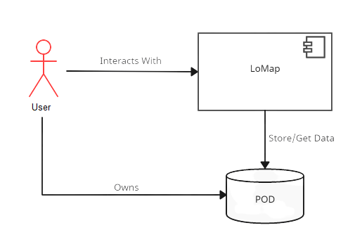
5.1. Whitebox Overall System
- Motivation
-
LoMap is an application that has a system where users can add custom places to the map. All the private data the application needs its stored in his personal POD.
- Contained Building Blocks
| Name | Description |
|---|---|
User |
The user that interacts with the application. |
LoMap |
The main application that is develop to be used by the user. |
Pod |
Personal POD of the user where the data is stored. |
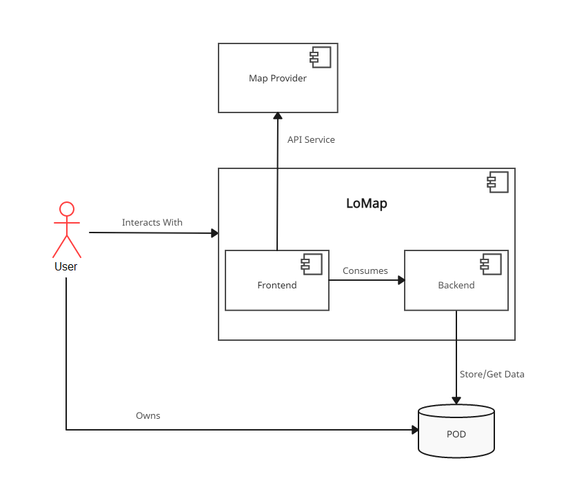
5.2. Level 2
- Motivation
-
We need to know how the LoMap service is built internally. As we see in the diagram we show the difference between the part of the application where the user interacts, and the part of the application that manages the data.
- Contained Building Blocks
| Name | Description |
|---|---|
Backend |
The place where the data is managed. |
WebApp |
User interface of the system that the user uses to interact with the application. |
Map Provider |
API that provide as the map interface for the main application. |
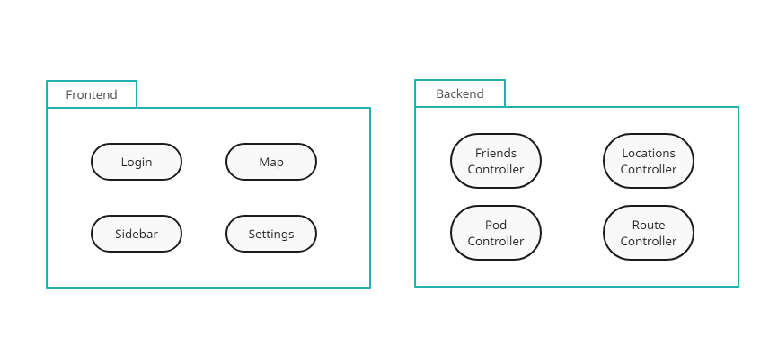
5.3. Level 3
- Motivation
-
To study in more detail how the WebApp works, that is the part that user interacts with, and also the Backend, the manager of the data.
- Contained Building Blocks
| Name | Description |
|---|---|
Login |
Page of the application where you can login. |
Map |
Main page where the map is display and the user can interact with. |
Sidebar |
Part of the main page where the data is shown. |
Settings |
You can change between different settings. |
FriendsController |
Management of the friends data. |
LocationController |
Management of the places data. |
PodController |
Management of the pod data. |
RouteController |
Management of the routes data. |
6. Runtime View
6.1. User Login and Logout.
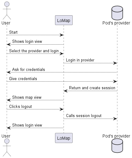
A new user or a returning user enters the application.
6.2. Return all location of the map.
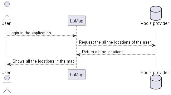
A user logs into the application and the first thing the application do is load all the locations.
6.3. Add location to the map.
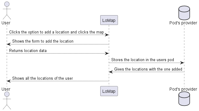
A user adds a new point
6.4. Delete location of the map.
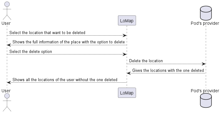
A user deletes an existing point
6.5. Modify location of the map.
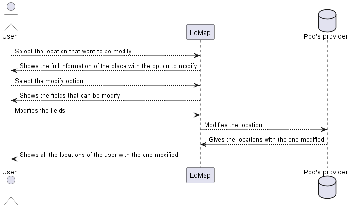
A user modifies an existing point
6.6. Send friend request.
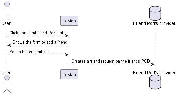
A user sends a friend request.
6.7. Accept a friend request.
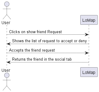
A user accepts a friend request.
7. Deployment View
7.1. Infrastructure Level 1
- Motivation
-
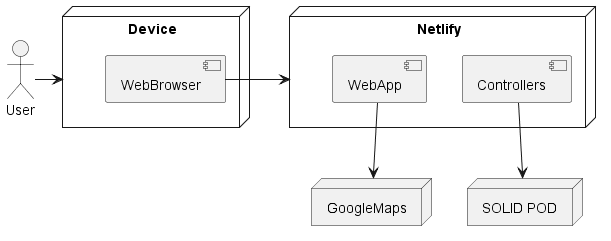
During the development of the application it runs on each person’s machine. However, the final product, it’s been executed on a server hosted with Netlify.
- Quality and/or Performance Features
-
Our application depends on many different APIs, some of them are to show the map and to manage the PODs. We cannot control these APIs, so the availability and efficiency of the application may be affected. Also, these quality features could be affected by the server.
- Mapping of Building Blocks to Infrastructure
| Block Name | Description |
|---|---|
Netlify |
Is in charge of the web access of the application |
GoogleMaps |
API that provides us the map where the user is going to operate the application and manage all the data. |
SOLID POD |
Personal and private data storage that each user has. All the private data that the user needs for the application or the data that the user generates it’s going to be stored here. |
Device |
Device that the user is going to use. Should need internet connection. |
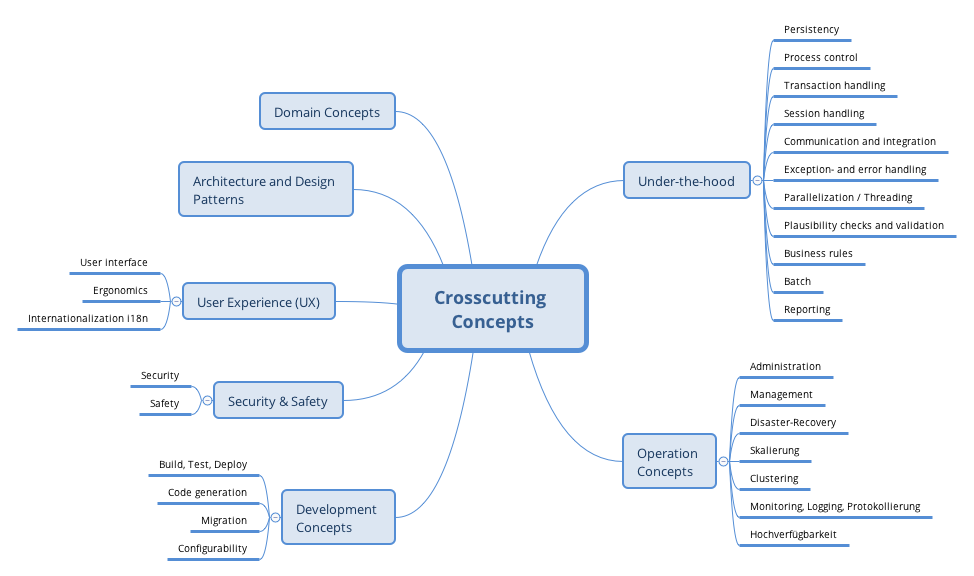
8. Cross-cutting Concepts
This section describes overall, principal regulations and solution ideas that are relevant in multiple parts (= cross-cutting) of your system. Such concepts are often related to multiple building blocks. They can include many different topics, such as
-
domain models
-
architecture patterns or design patterns
-
rules for using specific technology
-
principal, often technical decisions of overall decisions
-
implementation rules
Concepts form the basis for conceptual integrity (consistency, homogeneity) of the architecture. Thus, they are an important contribution to achieve inner qualities of your system.
Some of these concepts cannot be assigned to individual building blocks (e.g. security or safety). This is the place in the template that we provided for a cohesive specification of such concepts.
The form can be varied:
-
concept papers with any kind of structure
-
cross-cutting model excerpts or scenarios using notations of the architecture views
-
sample implementations, especially for technical concepts
-
reference to typical usage of standard frameworks (e.g. using Hibernate for object/relational mapping)
A potential (but not mandatory) structure for this section could be:
-
Domain concepts
-
User Experience concepts (UX)
-
Safety and security concepts
-
Architecture and design patterns
-
"Under-the-hood"
-
development concepts
-
operational concepts
Note: it might be difficult to assign individual concepts to one specific topic on this list.
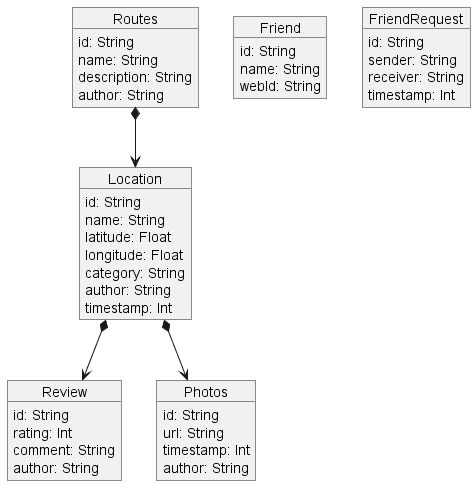
8.1. Domain model
8.2. Main architecture
The main architecture of the application is an MVC.
8.3. Privacy
One of the main goals of the entire application is the privacy of the users. For this we use SOLID technology called PODs, which stores data and the user decides the privacy of the data. Users can enter the app by login with their POD provider.
8.4. User Interface
We use the React library in combination with JavaScript for the front-part of the application. The user interface should be simple to use, have a clean appearance and be easy to navigate.
8.5. Internationalization
The application is developed to be used by many people who can use different languages, because of this the whole app can switch the language between Spanish and English.
9. Design Decisions
| Design Decision | Pros | Cons |
|---|---|---|
React |
A useful library widely used in large companies with lots of facilities and examples. It is an easy library to learn and also makes user interface development easy. It also has high compatibility with SOLID technologies. |
It is the first time we use this technology, it is easy to learn to use it, but it is difficult to master it. In addition, official documentation is missing. |
JavaScript |
We have previous experience with this technology, and it allows us a lot of freedom in development in combination with React |
The freedom it provides can also be a major drawback, as it can cause weird errors with type handling. Also, it can cause some problems when reading new code developed by other members of the group. |
GoogleMaps |
It is a free library that has a lot of customization and facilities for the map, we also have previous experience with it |
Although it is free to use, it is limited to a time and uses, so if it is going to work for a long time, we will have to pay. |
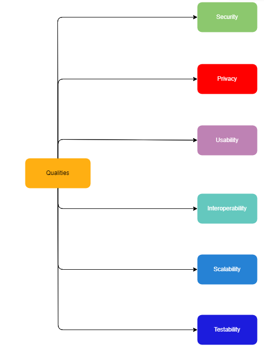
10. Quality Requirements
10.1. Quality Tree
10.2. Quality Scenarios
| Scenario | Quality Requirements | Quality Scenarios |
|---|---|---|
A user tries to modify other users data |
Security |
The data that the user storages or uses in the application must be protected and only modifiable by the user o others that the user authorized. |
A user adds information that is not public and will only be available to the users he has granted permissions to access |
Privacy |
The user provides to others and to the application only the information the owner wants. |
A new user enters the application for the first time |
Usability |
The application must ensure that new users know in little time how to use the basic functionality. |
A user adds information in another app that follows the same data structure |
Interoperability |
LoMap has to be able to use the information stored by other applications as long as the data structure is the same. |
New functionality is needed |
Scalability |
The application must be developed always thinking that this is not the final product, and we can always add new functionality. |
Some functionality of the application is not running correctly |
Testability |
Tests will run to prevent functionality from not working as intended, even if new functionality is added. |
11. Risks and Technical Debts
11.1. Risks
| Risk | Description | Measure |
|---|---|---|
Big Project and Time |
Being a large project compared to the projects we have done so far, the magnitude and the time we have are two of the things that we need to have in mind. |
Being aware of the time, deadlines and also, have a good atmosphere in the team, solve the problems we encounter and support each other during the development. |
SOLID knowledge and usage |
The project uses the SOLID technology, called PODs, to store the data that the user uses in the application, this is a new technology that we need to understand and use. Also, we are very susceptible to changes in the SOLID technology that can cause bugs |
Read the documentation and see examples of the usage of SOLID. Trust that SOLID works properly and we have the methods to control those errors and notify them. |
Usage of new technologies |
As well as SOLID is something new for us, we also are using other technologies that we never used before |
This can be mitigated with some experience that we will gain when developing the application, reading all the available documentation that we will need and seeing examples |
11.2. Technical debts
| Technical debts | Brief description |
|---|---|
Lack of experience |
None of the team members have any experience in the use of technologies such as: React, Node, Solid… , which means that we have to make an initial effort to learn these technologies. |
12. Glossary
| Term | Definition |
|---|---|
Solid |
Solid is a project that aims to radically change the way Web applications work today, resulting in true data ownership as well as improved privacy. |
POD |
Personal data storage that is not kept in the application, is on cloud and the user decides what information the application uses. |
React.js |
React is an open source Javascript library designed to create user interfaces to make it easy to develop single page applications. |
API(Application Program Interface) |
External service that provides some functionalities that makes our development easier. |
IDE |
Software application that provides facilities for software development. |
About arc42
arc42, the Template for documentation of software and system architecture.
By Dr. Gernot Starke, Dr. Peter Hruschka and contributors.
Template Revision: 7.0 EN (based on asciidoc), January 2017
© We acknowledge that this document uses material from the arc 42 architecture template, http://www.arc42.de. Created by Dr. Peter Hruschka & Dr. Gernot Starke.