
1. Introduction and Goals
LoMap is a software system being developed as a university project. It is designed to help citizens create personalized maps of places and local businesses in their city.
The aim of the project is to develop a generic software solution that can be deployed and used in other cities as well. The system will allow users to add locations in different categories like shops, bars, restaurants, sights, monuments, etc. and show them in a map window. Users will also be able to add review scores, comments, pictures, and more about the added places. The shared information will be stored in a personal pod according to the SOLID project.
The project’s initial focus is on the user, allowing them to create their personal map of the places they live. Users can manage the information that is accessible to either themselves or all of their friends. The system will allow users to see places and information about those places taken from their friends.
1.1. Requirements Overview
All LoMap Users will be able to:
-
✓ Add locations in different categories like shops, bars, restaurants, sights, monuments, etc.
-
✓ Add review scores, comments, pictures, and more about the added places.
-
✓ See places and information about those places taken from their friends
-
Users will be able to decide, then, if their posts are shared with their friends only or remain accessible to themselves only.
-
In further of stages of the project:
-
✓ Establishment owners and public entities will be able to create public map locations for their businesses
-
✓ Users will be able to decide what city are the living in.
-
✓ Users will be able to personalized the set of friends the locations will be shared to.
-
Keeping privacy in mind, all of the above, will be supported by the SOLID project specification , making use of SOLID Pods for individual data storage. This way, users will be in full control of which information they share and of who they are sharing it to.
More details are described in the following document: LoMap Assigment Description
1.2. Quality Goals
| Goal | Description | Example |
|---|---|---|
Privacy |
Data will only be shared with those parties the owner agrees to. |
The user pins his/her own home in the map, and wants it to remain private, and not accessible to other users. It will be stored in his/her own POD, and won’t be shared with any other user nor party. |
Responsiveness |
LoMap will adapt it’s size and content distribution to the device it’s being accessed to, so usability is ensured. |
User want’s to know the general opinion of a local restaurant of a city she’s visiting. She owns an old , small-screened phone, and so , LoMap contents will change their layout so this user can navigate successfully though it. |
1.3. Stakeholders
| Role/Name | Contact | Expectations |
|---|---|---|
Product owners |
José Emilio Labra Gayo, Pablo González González , Irene Cid Rico , Cristian Augusto Alonso |
They’ll provide the project with architectural guidance, constraints and requirements. |
Citizen Users |
- |
To be able to intuitively pin places, leave reviews and rate places they visit. To be able to modify or remove any of the mentioned before. To establish a network of contacts that can access their content as well as being able to access those contact’s information. To be able to revoke connections and to stop sharing information with them. To access public content posted by any other user / organization. To create several custom maps. To filter data displayed. |
Business Owner Users |
Representative figure (CTO, CEO..) depending on the business. |
(FURTHER STAGES OF THE PROGRAM) To be able to create map locations for their business, so potential visitors and customers can access them. |
Each city’s council |
Representative figure (Major, secretary, governor) depending on the location. |
To boost the popularity and tourism of the city , by making it easier for foreigners to discover good places. To give citizens a chance to discover new places. The application would have to complain certain specifications, for example, being secure. |
HappySw FrontEnd Engineers |
Juan Manuel González Sierra, Manuel Hernández Cuartas, Sebastián Radu, Batuhan Bayir, Sara Fernández Arias |
They require to know the architecture in order to develop the user interface as well as to communicate it with other parts of the system. Also some constraints could take an effect on frontend decisions. |
HappySw Backend Engineers |
Juan Manuel González Sierra, Manuel Hernández Cuartas, Sebastián Radu, Batuhan Bayir, Sara Fernández Arias |
In order to develop lower layers of the design, such as data management and business logic, these engineers will require to know all aspects of the system’s architecture. |
HappySw Testing Engineers |
Manuel Hernández Cuartas,Juan Manuel González Sierra, Manuel Hernández Cuartas, Sebastián Radu, Batuhan Bayir, Sara Fernández Arias |
In order to test that the system is behaving as expected, engineers need to know how it is expected to work in the first place, and so, how not. For that, they’ll need to have detailed knowledge about the system’s architecture. |
Existing SOLID-based applications |
Other group’s members. See LoMap_enX or LoMap_esX on GitHub. Inrupt, & other pod providers. |
To develop an application whose pods can communicate with other SOLID oriented applications. |
2. Architecture Constraints
2.1. Technical constraints
Constraint |
Explanation |
Maps should be under full control of the users |
One of the main focuses of the application is the user, therefore all the maps created and personalized by them should be under their full control. |
Use of pods |
Following with the users' focus, all the shared information by them should be stored in their corresponding personal pods according to the SOLID project, guaranteeing their real ownership of such information. |
Web application |
LoMap is mainly a web application, making it easy for most if not all users to use and access the application. |
Generic software solution |
The idea is to develop a generic solution that could be deployed in any city needed, not just an exclusive solution to one city. |
GitHub |
Use of a repository regarding version control. |
2.2. Organizational constraints
Constraint |
Explanation |
Budget |
The team is not getting any budget whatsoever, so if there is a need to pay for something, it will run on the members of the team. |
Delivery deadlines |
There are 4 deliverables every 3 weeks that should be followed accordingly before the deployment of the application. |
2.3. Conventional constraints
Constraint |
Explanation |
ARC42 |
Documentation format must follow the ARC42 standards. |
English |
The project must be developed in such language. |
3. System Scope and Context
LoMap is a Software system where citizens can hav personalised maps about places and locals businesses in their city. The personalised maps will be under full control of the users and the shared information will be stored in a personal pod according to the SOLID project.
LoMap is a generic software solution that can be deployed and used in other cities. It is focus on the user but it also allows places to create their own space, like a digital version of their physical place.
3.1. Business Context
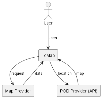
LoMap software manages information from user’s POD and displays information from places in a map. In order to do that it need a map to display and a way to access to the user’s data.
Since it is a generic software solution, it communicates with two partners to satisfy this requirements.
First we need a map provider, that is because we want LoMap to be flexible to changes so we can change the city it displays without needing a big database with all this data stored by our system. And second, a POD Manager, that will help us with authentication and data manipulation.
Business context’s diagram
External domain interfaces We will mainly use two resources for the map:
-
Google maps
-
Inrup’s Solid React library
And for managing the user’s data a React’s library that uses the Inrupt Javascript Client Libraries (Solid React SDK - solid-ui-react).
Communication partner |
Inputs |
Outputs |
geographical coordinates and a zoom level |
map object |
|
solid-ui-react (Inrupt) |
podURL, session |
datasets/things |
3.2. Technical Context
We have decided to develop LoMap as a React Application, using express as a package manager. No Database , we will fully relly on the pods.
One of the goals is the decentralization of the application. This is done thanks to the PODs that will help us to ensure user’s privacy.
Users are the ones that own and manage the access to their information, not the application itself. To handle this, each user will be the owner of a Solid POD (Personal Online Data Store) from which the required information is extracted.
Technology |
Explication |
React |
React is a free and open-source front-end JavaScript library for building user interfaces based on components. We use it to develop the website in frontend. |
JavaScript |
Is the programming language used for the development. It is one of the core technologies of the World Wide Web. |
SOLID |
Is used to store each users data in a POD. |
3.3. Technology decisions
-
Implement LoMap in mainly a React framework with a Express server. React is a really suitable framework for the use of pods and also for the developing of one page applications.
-
Javascript: The programming language we chose was Javascript as none of us had any experience with neither Javascript or Typescript and we thought the learning curve of the first one could be a bit easier to deal with.
3.4. Decisions about the top-level decomposition of the system
-
Do not have a database: During the development process we found ourselves not needing a centralised database. This is mainly because our top quality goal was privacy and to get such goal the use of the pods to store every piece of information of the user was the best approach in our eyes. It keeps the information of the user decentralised and at their disposal at all times.
-
This makes our application mainly client-side, with a server using just express.
-
No REST API needed.
3.5. Decisions on how to achieve key quality goals
-
Use Google Maps API regarding the maps of the application. Brings us a nice infrastructure regarding every location aspect of the application we could need.
-
Use the corresponding APIs in order to establish proper connection with the pods.
3.6. Relevant organizational decisions
-
Use of git workflow regarding version control. This way we can have a great amount of control over the versioning and updating of the code when developing the application.
-
Constant review and update of the projects documentation in order to develop an easy to understand application for other developers (not only potential users).
-
Delegate in the solid provider all the possible actions related to the pods, such as login, management of the adding and removing of friends or the users' own profile.
4. Building Block View
The building block view shows the static decomposition of the system into building blocks (modules, components, subsystems, classes, interfaces, packages, libraries, frameworks, layers, partitions, tiers, functions, macros, operations, data structures, …) as well as their dependencies (relationships, associations, …)
This view is mandatory for every architecture documentation. In analogy to a house this is the floor plan.
Maintain an overview of your source code by making its structure understandable through abstraction.
This allows you to communicate with your stakeholder on an abstract level without disclosing implementation details.
The building block view is a hierarchical collection of black boxes and white boxes (see figure below) and their descriptions.
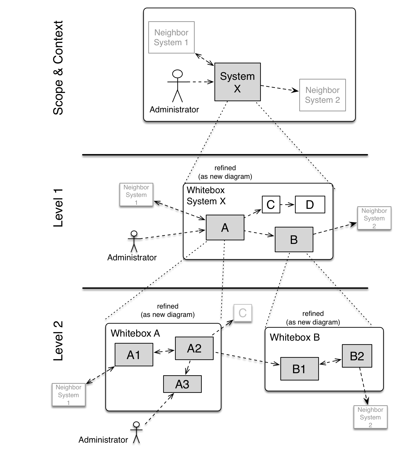
Level 1 is the white box description of the overall system together with black box descriptions of all contained building blocks.
Level 2 zooms into some building blocks of level 1. Thus it contains the white box description of selected building blocks of level 1, together with black box descriptions of their internal building blocks.
Level 3 zooms into selected building blocks of level 2, and so on.
4.1. Whitebox Overall System
Whitebox Overall diagram
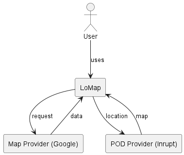
The section shows the static decomposition of the system into building blocks as well as dependencies. We are following SOLID architecture, so the system will have three main sections which communicate between them: 1. LoMap: allows users to manage personalised maps 2. Map Provider: provides the app with a map to display 3. Data Access Provider: gives access to user’s data
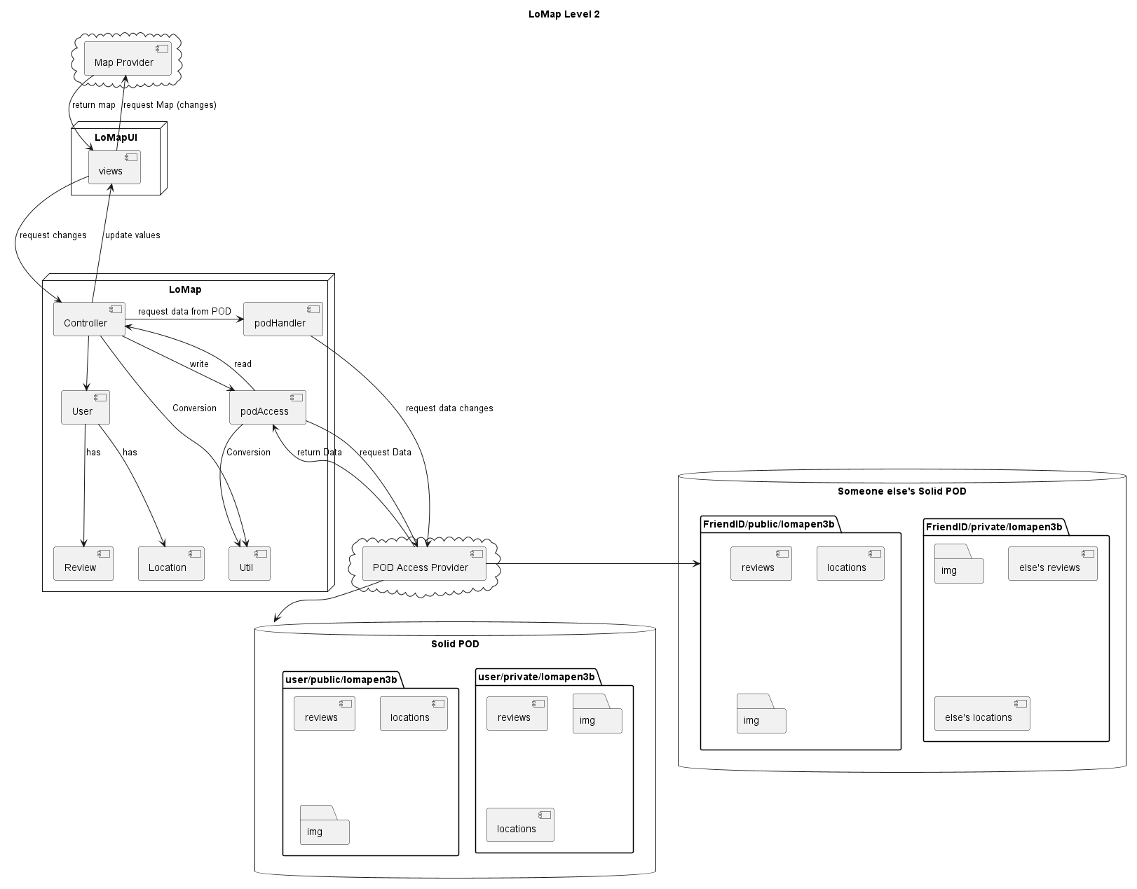
4.2. Level 2
In this view, we have a representation of the components of the system from a standpoint of the each module’s dependencies. Level 2 diagram
5. Runtime View
All runtime scenarios where developed based on the SOLID project documentation
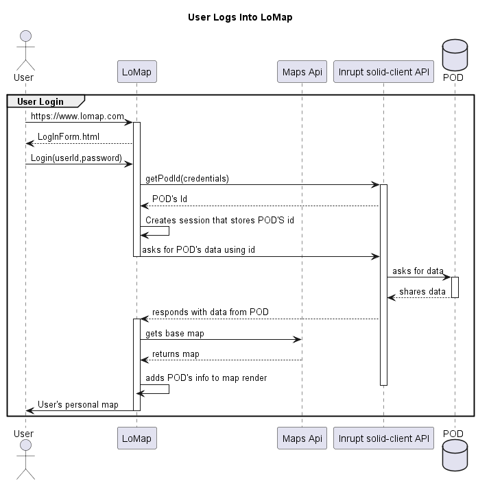
5.1. <Runtime Scenario 1 - User login>
-
The user logs into LoMap, by using his POD credentials.
-
Credentials will be validated by making a petition to the POD provider (INRUPT) api
-
LoMap checks the session’s Login status.
-
If the data is correct, a new session will be started, and lomap will display the user’s map.
-
In case the data is not found, user will be notified. No session will start.
-
-
-
5.2. <Runtime Scenario 2 - User adds private elements to the map>
Location Addition Deletion & Updating will work in a similar way architecture-wise. In general terms, the process will be the following :
-
Petition to the Inrupt api using the POD’s ID.
-
Inrupt api will communicate with the pod, depending on the endpoint, it will ask the pod to add, update , delete or just retrieve information.
-
In case of addition/deletion/update , LoMap will ask the POD to return the updated data (through Inrupts api)
-
Once LoMap receives the updated data, the map will be rendered again.
Below, a sequence diagram for Additions it’s provided
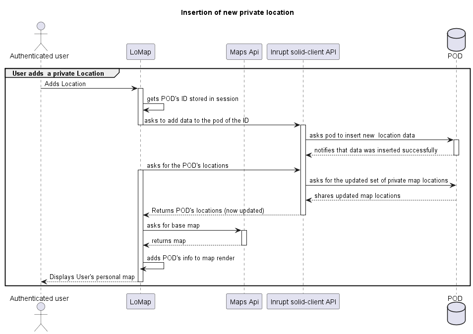
For the sake of simplicity, friend’s locations CRUD & display will be covered in an independent runtime scenario.
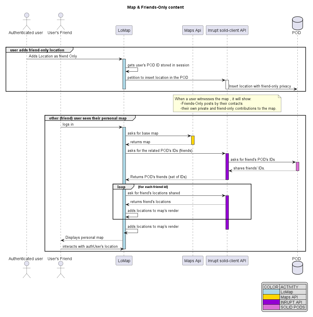
5.3. <Runtime Scenario 4 -Privacy levels >
LoMap will provide the users with TWO privacy levels at the moment:
-
Friends-Only posts will only be displayed to their contacts
-
Private contributions will appear to the creator only.
In further stages, a new privacy level will be implemented:
-
Public contributions to the map will be shown to any user.
The references to Friend users are stored in the Pod
-
That means that, to display friend content, a petition to the pod will be made to ask for the set of friends of a user.
-
LoMap will retrieve the locations set as friend-only by each contact from the pod and then add them to the user’s personal rendered map.
-
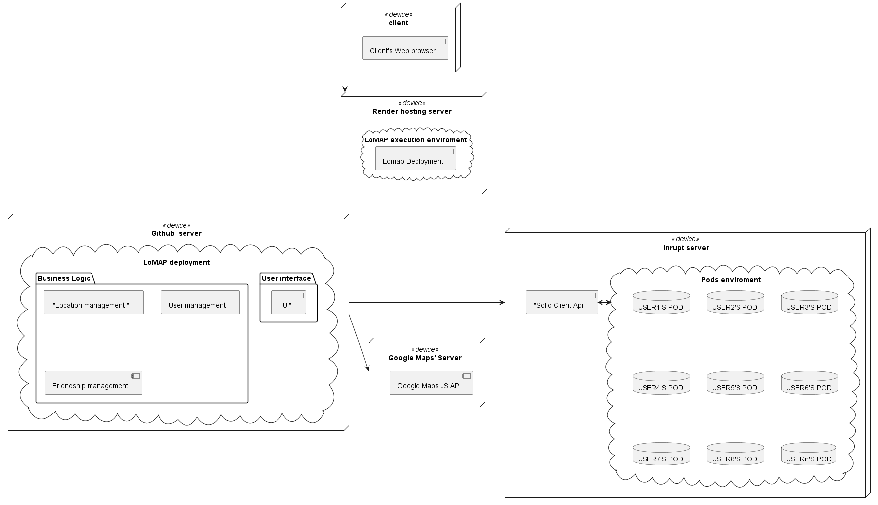
6. Deployment View
6.1. Infrastructure Level 1
<Overview Diagram>
- Motivation
-
In order to provide clients with a better understanding of the communication between system modules.
- Quality and/or Performance Features
-
We’ve chosen these modules in order to keep architecture easier to maintain , and therefore to have more control over attributes as privacy , scalability..
- Mapping of Building Blocks to Infrastructure
| Element | Description |
|---|---|
Render |
Hosting service |
GitHub |
Repository where LoMap’s source code is stored. |
MongoDb |
LoMap’s database for public information |
Business Logic |
Set of LoMap’s application modules. |
User interface |
Frontend of the application that will communicate with pod provider’s and user IO |
Solid client api |
Inrupt’s api LoMap will use to communicate with pods. |
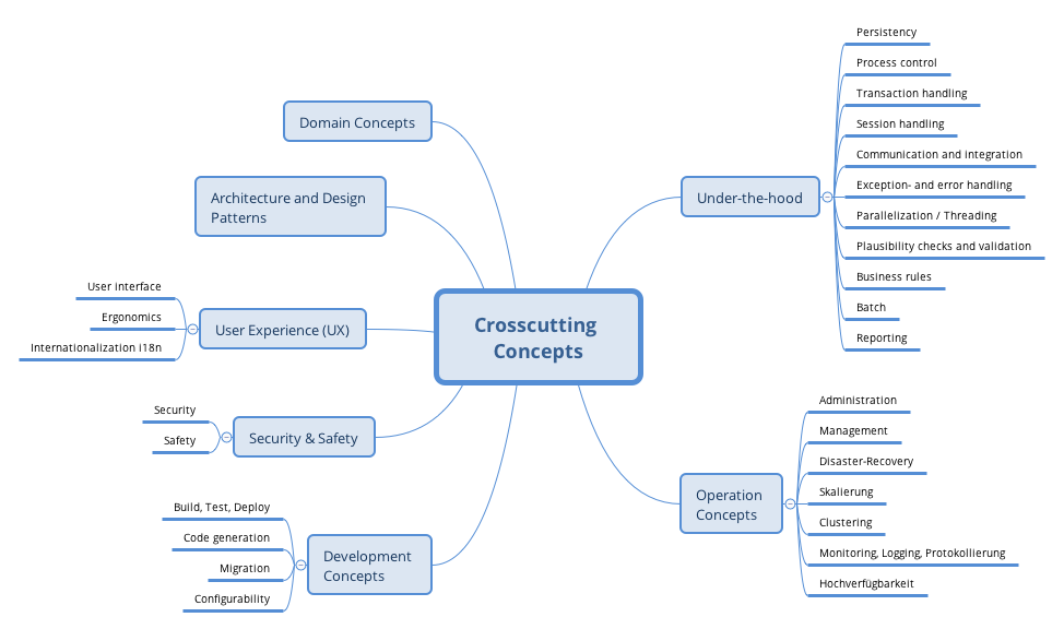
7. Cross-cutting Concepts
This section describes overall, principal regulations and solution ideas that are relevant in multiple parts (= cross-cutting) of your system. Such concepts are often related to multiple building blocks. They can include many different topics, such as
-
domain models
-
architecture patterns or design patterns
-
rules for using specific technology
-
principal, often technical decisions of overall decisions
-
implementation rules
Concepts form the basis for conceptual integrity (consistency, homogeneity) of the architecture. Thus, they are an important contribution to achieve inner qualities of your system.
Some of these concepts cannot be assigned to individual building blocks (e.g. security or safety). This is the place in the template that we provided for a cohesive specification of such concepts.
The form can be varied:
-
concept papers with any kind of structure
-
cross-cutting model excerpts or scenarios using notations of the architecture views
-
sample implementations, especially for technical concepts
-
reference to typical usage of standard frameworks (e.g. using Hibernate for object/relational mapping)
A potential (but not mandatory) structure for this section could be:
-
Domain concepts
-
User Experience concepts (UX)
-
Safety and security concepts
-
Architecture and design patterns
-
"Under-the-hood"
-
development concepts
-
operational concepts
Note: it might be difficult to assign individual concepts to one specific topic on this list.
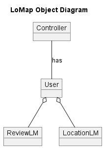
7.1. Domain model
7.2. Architectural and design patterns
For this application we choose to use the Modular Monolith Architecture. The modular monolithic architecture consists of dividing our logic first into modules, and each module will be independent and isolated. Then, each module should have its own business logic. The system will only have one database. The two modules the app is using is Locations and reviews. The are being stored into the POD independently and also retrieve. Even though we have some logic to keep things stuck together since a review must have a location associated, also we must be done by a user.
7.3. Testability
We will use Unit Testing in order to assume that the development of this application goes as planed without having any functioning issues. Before implementing a new functionality we must be sure that the actual version of the application passes all our test and satisfies all our scenarios until that moment. We will test separately every part of our code.
7.4. Protection and Security
One of the main priorities of LoMap is to ensure our clients a about their privacy giving them the option to choose with who they want to share their data. The app will be secure as every user’s data will be safely saved in a POD.
Everybody using the app should trust it.
8. Design Decisions
8.1. Architectural Decision Record
| Decision | Description |
|---|---|
Using a MERN STACK |
Horizontal scalability . Good choice for real-time apps. |
Using Render as a hosting service |
Offers free hosting with integrated continuous deployment. Https granted too. |
Having two privacy levels : Just for friends and private. |
To allow the user to decide which people he/she shares the locations with. |
Using Just React and Express |
We will rely on solid pods, so we don’t need to provide an api + Privacy. |
Folder structure |
We will take advantage of the pods folders "public" & "private". Inside each one we will create the folder for the private section of lomap, and the folder for the locations shared with friends. |
Usage of Azure as a hosting service |
Render required organization permissions to apply continuous integration since it was a third part app. Azure is just fine for the time our app will be deployed. |
8.2. Folder structure
In order to avoid collisions with other lomap applications, and so , allow our users to be able to use several LoMap solutions, we have thought of the following
POD:
    Public:
        --LoMapEn3b:
            --Pictures:
                -beach.png
            --Locations.ttl
            --Reviews.ttl
    Private:
        --LoMapEn3b:
            --Pictures:
                -Selfie.png
            --Locations.ttl
            --Reviews.ttl
8.3. Hosting service
Regarding hosting services , we’ve balanced the following options:
| Hosting service | Pros | cons | Using it would imply… |
|---|---|---|---|
Heroku |
Used to offer free hosting |
Not free hosting offered anymore |
Paying - immediately rejected. |
FireBase |
Security. SSL Certifcate. Works nice with React. Free hosting. |
Serverless ( for our architecture is a con) |
Since we don’t plan on going serverless , we would have to connect to the DB from the client using JS. Messy. Specially risky, since SOLID PODS require https. Other option is to go serverless. |
Azure |
Free credits given by university. We used it already. Security. Compatibility. |
Credit card info has to be provided even for free services. Machines consume credit each minute being used, and in order to spend 0 credits we would need to delete the machines. |
Being really mindful of credit left. We are not really sure if it would be compatible with continuous deployment, since that would require the service to be working. We would probably run out of credit. |
Amazon Web Services |
Free credits given by university. Used it in SEW. Security. Compatibility. Load Balancing & CDN |
The free version is not what it used to be, now , part of the credit has to be used to take some courses aws provides , not to spend it in personal projects. So that would probably end up in credit running out. |
Being really mindful of credit left. Having to make the tutorials. Just like azure, we are not really sure if it would be compatible with continuous deployment, since that would require the service to be working. We would probably run out of credit. |
Netlify |
Free services 300 build minutes/month 500 Websites can be hosted for free community forum |
Only one member for free |
Only one person would be able to deploy and access the management UI. So each time someone of us wants to make a deploy, he/she would have to ask the person designed. |
We knew no option could be perfect, specially when looking for free services. But we also knew, these options were not the best fit they could be…At least not if we did not go serverless.
The option chosen was Azure. There, we will create a virtual machine , that will host a docker container running , made from an image of our application.
In order for it to be compatible with Inrupt, we will use port 443(https) to serve our application.
In order to enable the https certificates required , we will use certbot, letencrypt and docker volumes to map the required directories.
9. Quality Requirements
9.1. Quality Tree
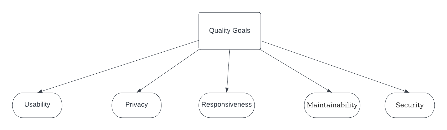
9.2. Quality Scenarios
Quality Requirement |
Scenario |
Priority |
Responsiveness |
The application needs to have a fast response time. Any user should be able to use the features of the app with no major problems and without having noticeable delays on response times. |
High |
Maintainability |
All of the code should be written in such a way that it can be easily modified and reused. Also, it is important that any errors or bugs can be easily fixed.LoMap will be developed minding the readability of its code and documentation. |
High |
Security |
The user’s data will be saved and retrieved from a secured pod. We want the users to trust our application with their private data. |
High |
Usability |
Our application will be easy to use for all types of users. It should be easy to understand and performing all the wanted actions shouldn’t raise any problems. |
Medium |
Privacy |
The user will have the option to choose with who he wants to share his data with. |
Medium |
10. Risks and Technical Debts
Risks |
Description |
Time |
We don’t have a very long time to develop the application so we need to organize ourselves in such way that we can do all the things that we propose. |
The team |
We didn’t knew each other before this project plus two of the team members are Erasmus students so we need to speak in english with is not our main language. |
The scale of the project |
It is the first time some of us are working in such a project that needs the knowledge of a lot of new technologies which some of us need to learn from 0. |
Technical debts |
Description |
SOLID API |
First time we hear about SOLID Pods so we have to document about them. |
JavaScript |
Some of the team members never used JavaScript. |
React |
It is a new JavaScript that all of us have to learn from 0. |
11. Glossary
| Term | Definition |
|---|---|
SOLID POD |
Solid Personal Online Datastores, or PODs, as “where you store your data… Once stored in a Pod, you control who can access your data.”. PODs can store any kind of data from text to videos to social networking data. You can think of PODs as “containers” for data, or even “digital twins” of users |
REACT |
React is a free and open-source front-end JavaScript library for building user interfaces based on components. |
Render |
Render is a unified cloud to build and run all your apps and websites with free TLS certificates, a global CDN, DDoS protection, private networks, and auto deploys from Git. |
API |
API stands for Application Programming Interface. In the context of APIs, the word Application refers to any software with a distinct function. Interface can be thought of as a contract of service between two applications. This contract defines how the two communicate with each other using requests and responses. |
Decentralization |
Are digital applications that run on a blockchain network of computers instead of relying on a single computer. |
JavaScript |
Is a scripting language that enables you to create dynamically updating content, control multimedia, animate images, and pretty much everything else. |
Node.js |
Is an open-source, cross-platform JavaScript runtime environment and library for running web applications outside the client’s browser. |
Express |
Express is a node js web application framework that is used to build a single page, multipage, and hybrid web application |
Stakeholder |
Are all individuals or groups who have a vested interest in the performance of the business. |
About arc42
arc42, the Template for documentation of software and system architecture.
By Dr. Gernot Starke, Dr. Peter Hruschka and contributors.
Template Revision: 7.0 EN (based on asciidoc), January 2017
© We acknowledge that this document uses material from the arc 42 architecture template, http://www.arc42.de. Created by Dr. Peter Hruschka & Dr. Gernot Starke.