1. Introduction and Goals
DeDe is a online shop project for the course of Software Architecture, University of Oviedo. We are the developers from team 3A, from the English group:
-
Pelayo González García
-
Martín Beltrán Díaz
-
Pablo García Fernández
-
Carlos Garriga Suárez
-
Josué Fernández Argüelles
-
Enzo Barbón Lema
DeDe (Decentralized Delivery) is an online shop developed following the SOLID project approach, allowing the users to store their personal information in decentralized and secure data storages, the so-called PODs. The shop itself won’t store any personal data from the users, but will ask them to provide a POD with their address, in order to send the purchased goods. If you want to know more about the solid project, do not hesitate to visit the SOLID project site.
1.1. Requirements Overview
The system will emulate an online shopping system where end-users can select and order products to buy. According to the distance between the distribution center and user’s address, the shop will calculate the total cost of the purchase and the delivery, and once the user pays, the order will be recorded and the delivery will be simulated.
The app will record each transaction and order, so a user can review orders done.
Needless to say, every time the app needs user’s location, the user should provide a POD, as our service does not store any shopper’s personal information.
1.1.1. Technical Deployment
DeDe will be implemented using TypeScript with React framework, and data will be stored in a Firebase database. The web service and deployment will also be provided by Firebase, since it provides 300$ bonus for students and a set of diagnosis tools to test loads and web performance.
1.2. Quality Goals
The top three quality goals for the architecture whose fulfillment is of the highest importance to the major stakeholders.
| Quality | Motivation |
|---|---|
Privacy |
DeDe should look after users privacy, not allowing them to store private data for deliveries (apart from the address), such as phone number, the receiver of the package, time laps when you can pick it up… |
Security |
Data such as account passwords or previous orders should be stored and only be accessible for the proper user. The database should also be protected against SQLInjections, and passwords must be encrypted. |
Availability |
As an online shop, DeDe doesn’t have an opening and closing time, so it must be working 24/7. |
1.3. Stakeholders
| Role/Name | Contact | Expectations |
|---|---|---|
Developers |
Martin Beltran, Josue Fernandez, Pablo Garcia, Pelayo Gonzalez, Carlos Garriga and Enzo Barbón. |
People in charge of developing the app. They expect to improve their software architecture knowledge and their designing and coding skills. |
Professors & Reviewers |
José Emilio Labra Gallo, Pablo González González |
They will guide the developers throughout developing process, providing tutorship and help when needed. |
Users |
People interested in buying products and good from our online shop. |
|
Previous year’s students |
Previous year’s projects may show the developers what an actual documentation and project development looks like, so they can find inspiration in those projects. |
|
Inrupt |
People that are inolved in Inrupt will have access to our project that is public in Github |
Empathy |
2. Architecture Constraints
The constraints will be divided into business and technical.
2.1. Technical Constraints
These constraints will limit the team’s ability to change the technology environment.
| Constraint | Explanation |
|---|---|
TypeScript |
TypeScript is the programming language in which the project has to be implemented. |
React |
The application must be implemented using the React Framework. |
Github |
The project must be constantly updated in GitHub, showing all the members collaborations. |
Arc42 |
The documentation must follow the Arc42 templates. |
SOLID |
The project will user SOLID user pods as data retrieval. |
Continuous integration system |
The application will be deployed using a continuous integration system. |
2.2. Organizational Constraints
| Constraint | Explanation |
|---|---|
Time |
The project must be done in 11 weeks. |
Team |
The team is composed of 6 members. |
3. System Scope and Context
3.1. Business Context
| Entity | Inputs | Outputs |
|---|---|---|
User |
The user’s input will be the interface provided by the webapp |
The outputs may be the POD generated by the user and also the information that will be received by the app |
POD |
The POD will store the users data in order to follow the SOLID project |
It will provide the information needed by the webapp |
Webapp |
The user will be able to make orders and also to access the information about their orders done |
The information that provides to the user logged |
Database |
The POD will have most of the information so we will not store it, but we will store other stuff like the products to buy |
Obviously the database will be linked to the web |
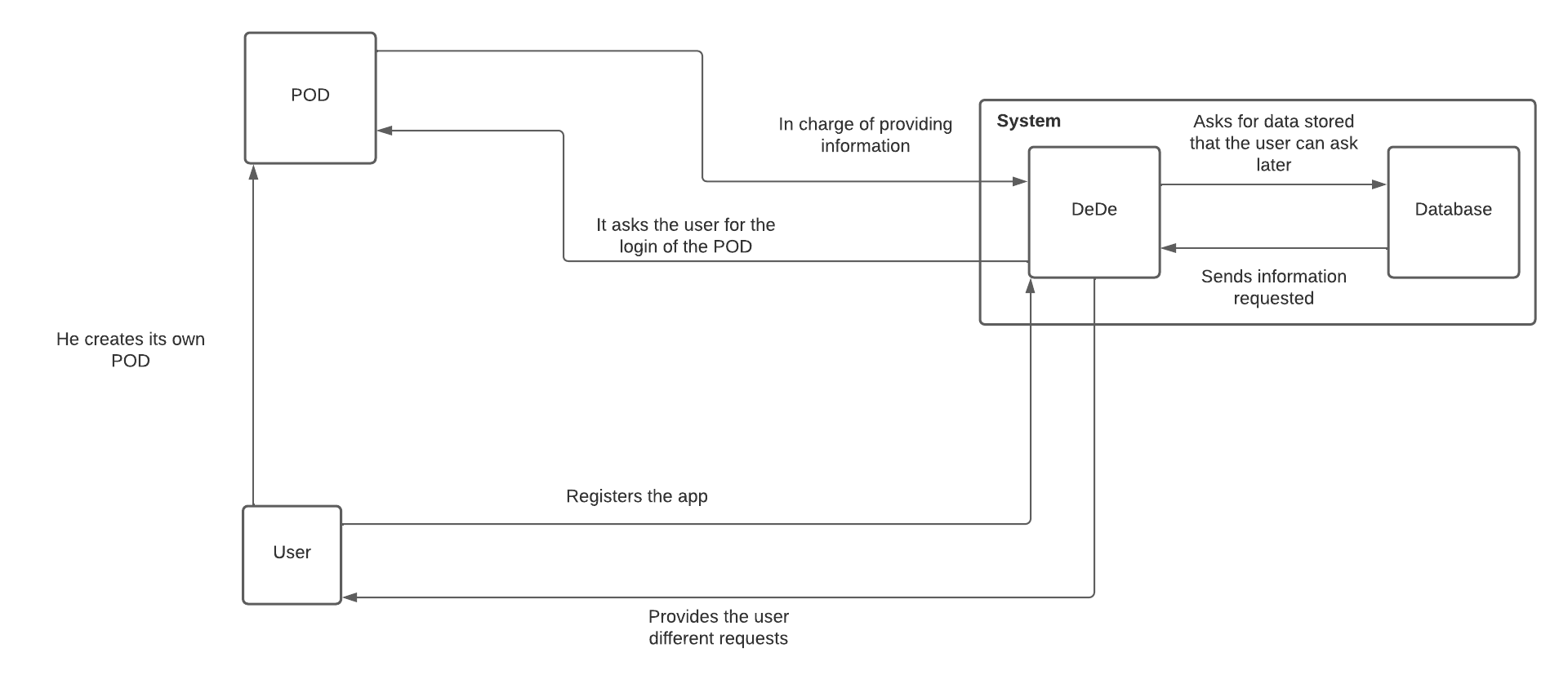
3.2. Technical Context
4. Solution Strategy
4.1. Technology Decisions
The technologies we have decided to use for the development of the app are:
Solid Community, Inrupt and SolidWeb → Main POD server providers. Widely used. The app works with all the PODs that follows the same standard as them.
Firebase → Serverless service for the deployment and development of the application, providing the web and DB hosting, a prepared backend for the DB and a way of deploying isolated custom functions. It also provides authentication storage, so user’s email and password (hashed) are safe and secure.
React and TypeScript have not been included in the list since it is compulsory to use them, and are not "a decision" itself.
4.2. Decisions about the top-level decomposition of the system
MVC → Probably the most common architectural pattern. It is used to decouple the interface, from the data and the domain logic.
4.3. Decisions on how to achieve key quality goals
Privacy → To achieve privacy, we won’t store any personal data from our users apart from their past orders.
Security → As users need to log in in the application, we will store their user’s passwords encrypted. Also, we plan to protect avery form field against SQL Injections by means of prepared statements.
Availability → Using an external reliable web-hosting service we ensure that the web and the database will be available almost 24/7.
4.4. Organizational decisions
To enable communication within the team members we have created a Discord Server for meetings and a Whatsapp chat group in order to schedule those meetings. We have refined tasks in a GitHub project, so we can follow the overall work and keep a backlog of the remaining tasks.
We also have an Issue system and a wiki, working as a log for decisions and minutes for meetings.
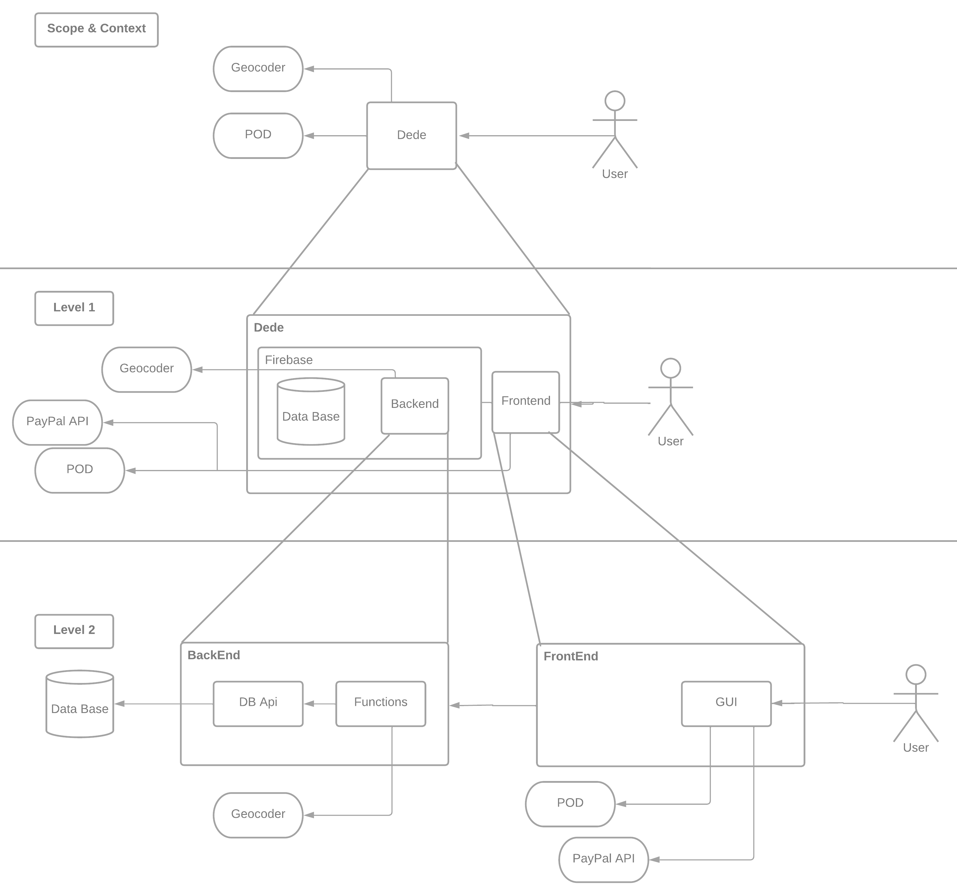
5. Building Block View
5.1. Whitebox Overall System
- Motivation
-
The building block view is meant to be as a quick overview of our application by making it’s structure easily understandable throught abstraction.
- Contained Building Blocks
-
Scope & Context:
User |
A client using our application. |
Dede |
The application itself. |
Pod |
The user’s pod. It is external to our application. It is used by the application in order to preserve the privacy of our users. Will be provided by an external POD Provider. |
Geocoder |
Api to calculate coordinates and distances given the address from the pod. |
PayPal API |
PayPal provides developers with a powerfull api to process payments with PayPal, Credit cards and Sofort. |
Level 1:
Frontend |
React application. Will contain the user interface as well as any client-side function the application may need. |
Backend |
The backend functionality will be provided by the firebase functions and Firebase DB Api. |
Level 2:
These components are highly subject to change, given the early stage of the application development
GUI |
The interface system the user will interact with. |
DB Api |
Built-in api already provided by firebase to access the database. |
Functions |
Provided by firebase. Serverless backend code that works via http requests. They allow JavaScript, TypeScript, Python and Go. They provide automatic vertical and horizontal escalation depending on the number of requests, ensuring availability and efficiency. |
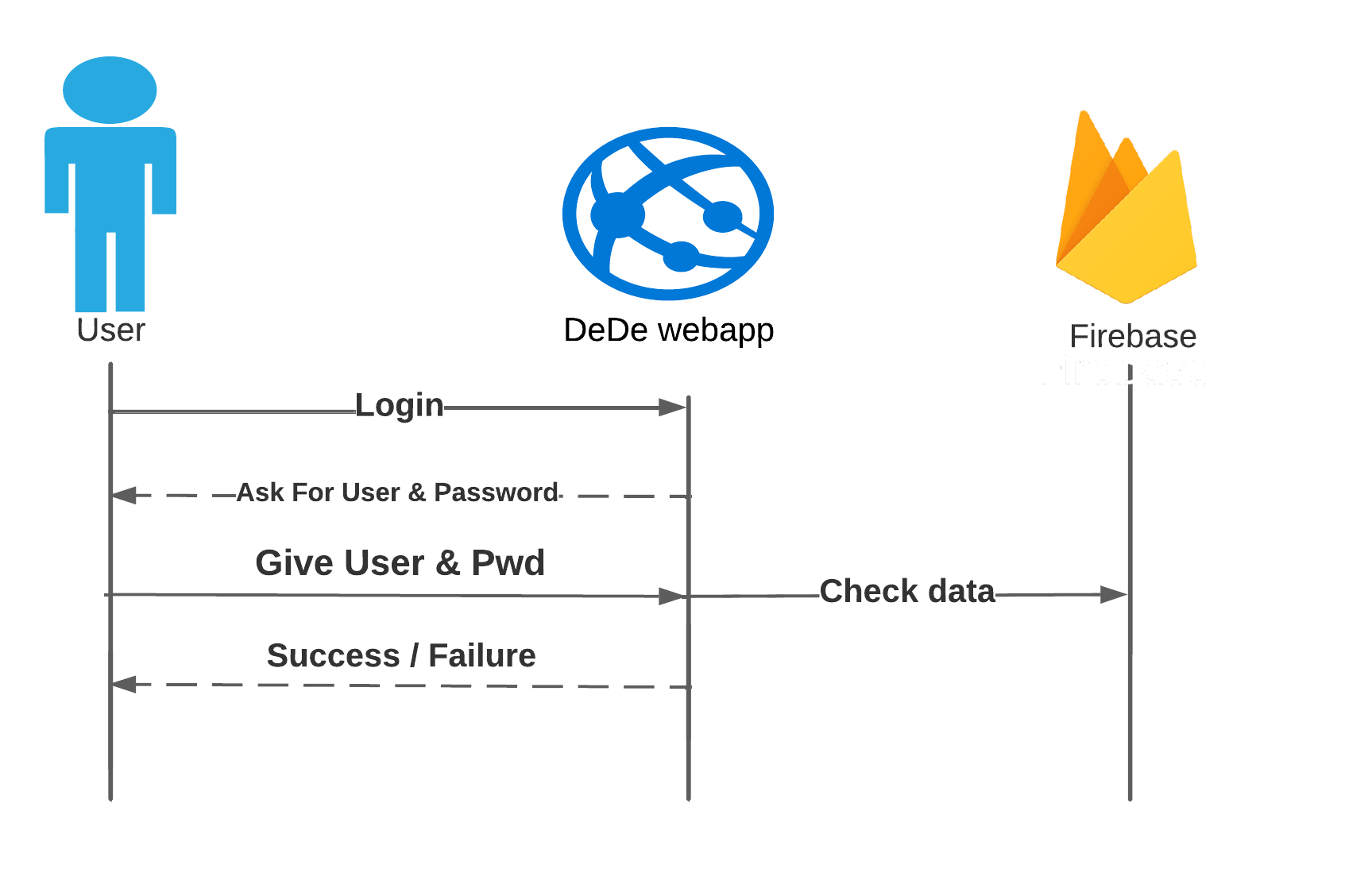
6. Runtime View
6.1. Login scenario
This is the process where the user logs in into the application and the system verifies it.
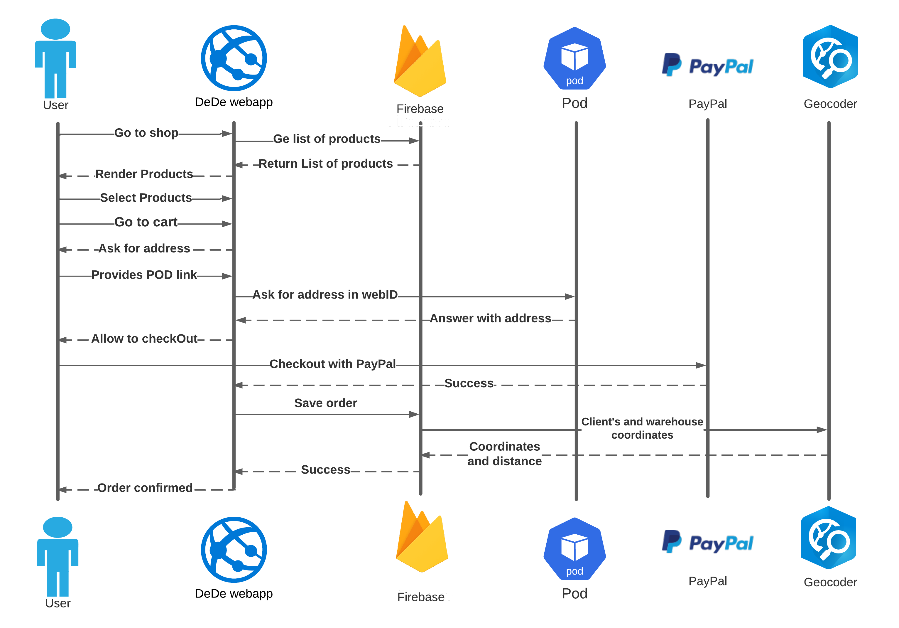
6.2. Purchasing scenario
Once the user has logged in he/she can purchase products, add them to the order and pay. This diagram represents a successful purchase.
7. Deployment View
7.1. Infrastructure Level 1
- Motivation
-
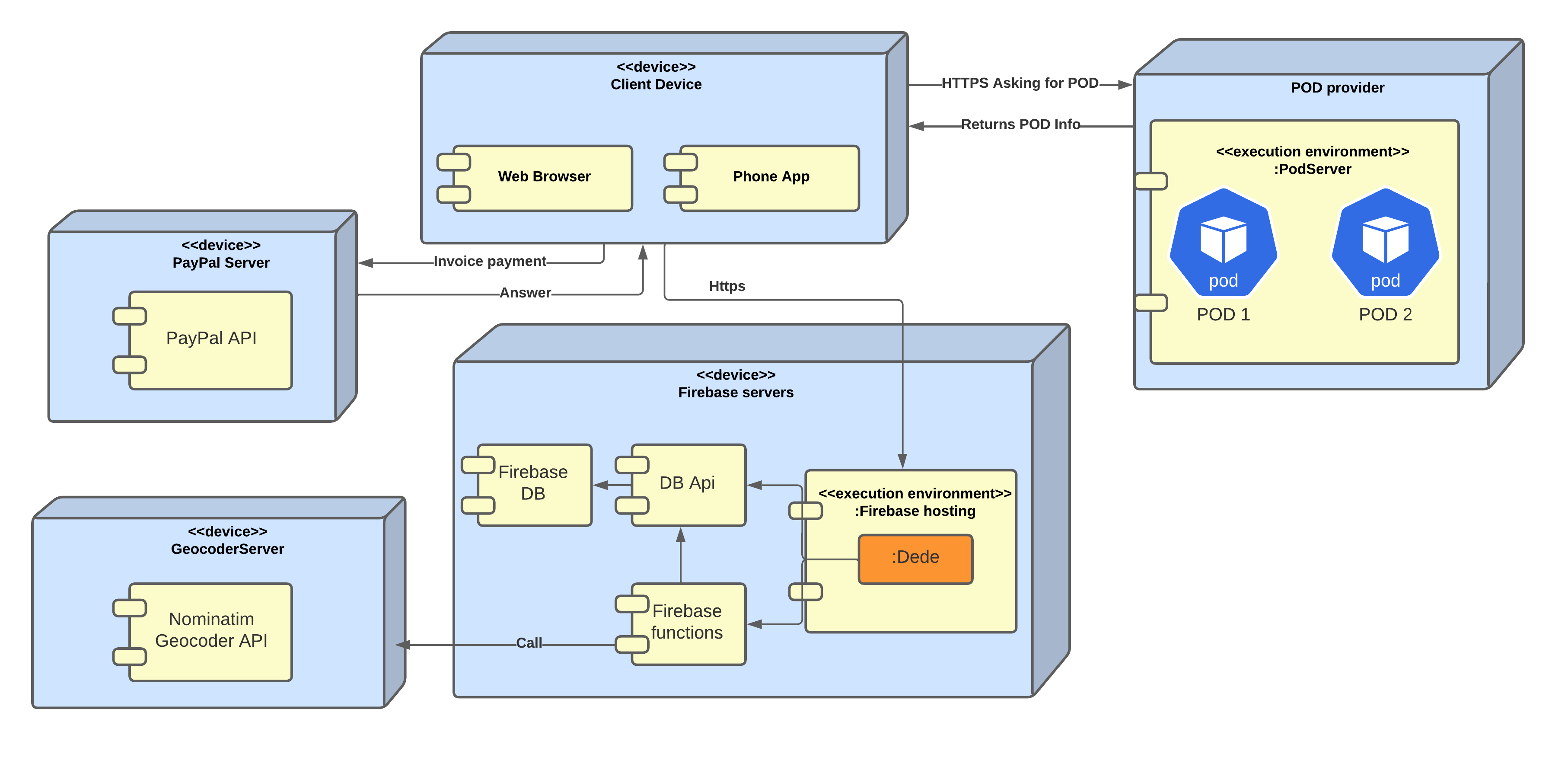
Software does not run without hardware. This underlying infrastructure can and will influence your system and/or some cross-cutting concepts. This diagram shows how the app components and their respective hardware devices are related to each other. It’s goal it’s to easily understand the technical infraestructure of the application.
- Quality and/or Performance Features
-
Performance is mainly based on the user’s available resources(connection speed, device hardware, etc.) and the resources of the hosting server device (which depends on the price plan). We cannot control those things. To a lesser extent, the performance of the application will also depend on the node.js and react apps. We will make the required optimizations in order to maximize the performance and quality.
- Mapping of Building Blocks to Infrastructure
Client Device |
Device of the user (desktop, mobile). Must have internet connection |
DB |
Firebase provides a database linked to the app. |
DB Api |
Corresponding api to perform queries to Firebase Database |
Web Server |
Firebase in which our app will be running. |
Geocoder |
Api to calculate coordinates and distances given a street, city, region… |
POD Provider |
The pod provider we will be using. In our case, Solid Community. Will be in charge of providing the pods for the app users. |
8. Cross-cutting Concepts
This section describes overall, principal regulations and solution ideas that are relevant in multiple parts (= cross-cutting) of your system. Such concepts are often related to multiple building blocks. They can include many different topics, such as
-
domain models
-
architecture patterns or design patterns
-
rules for using specific technology
-
principal, often technical decisions of overall decisions
-
implementation rules
Concepts form the basis for conceptual integrity (consistency, homogeneity) of the architecture. Thus, they are an important contribution to achieve inner qualities of your system.
Some of these concepts cannot be assigned to individual building blocks (e.g. security or safety). This is the place in the template that we provided for a cohesive specification of such concepts.
The form can be varied:
-
concept papers with any kind of structure
-
cross-cutting model excerpts or scenarios using notations of the architecture views
-
sample implementations, especially for technical concepts
-
reference to typical usage of standard frameworks (e.g. using Hibernate for object/relational mapping)
A potential (but not mandatory) structure for this section could be:
-
Domain concepts
-
User Experience concepts (UX)
-
Safety and security concepts
-
Architecture and design patterns
-
"Under-the-hood"
-
development concepts
-
operational concepts
Note: it might be difficult to assign individual concepts to one specific topic on this list.
8.1. Domain model - Simple Class Diagram
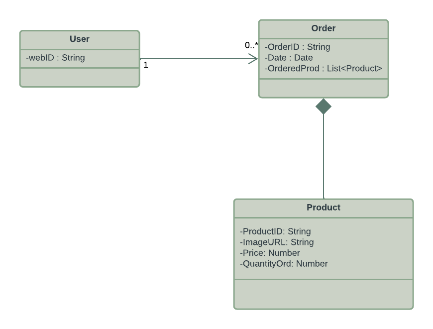
The main point of following this model is to allow the user to have a related lists of orders, containing the products purchased in that order and the date.
9. Design Decisions
| Decision | Pros | Cons |
|---|---|---|
QA-1 Webstorm |
Easy IDE to use very similar to IntellIJ |
|
QA-2 Webapp |
Better user experience, flexible access, easy setup. |
Reduced speed, Internet reliance. |
QA-3 Pod. Solid Community |
Data security, all data in one place. |
As the data is decentralized you need to rely on a different product and poor documentation. |
QA-4 Firebase Hosting |
It supports the deployment for the app. High availability. |
Not very familiarized. |
QA-5 Firebase Database |
It stores the document-based database. High availability. Provides a clear web interface to administrate it. A protected and secure backend for accessing the storage is already provided. |
Not very familiarized with document-based database. |
QA-6 Firebase Functions |
Serverless approach to provide the backend of our app. Has its own stored logs. High availability. |
Very difficult to debug. |
QA-7 Redux |
Easy way of keeping the state of the application and using information of different pages |
Hard configuration and none of us had any idea of how to use it before. |
QA-8 Geocoder API |
Fast coordinates resolution for addresses. |
Very poor documentation for using it in TypeScript. |
QA-9 PayPal API |
Reliable payment gateway |
A bit poor and unclear documentation |
10. Quality Requirements
In this section our goal is to develop with more detail what it was said in the point 1.2, going in depth with the quality attributes.
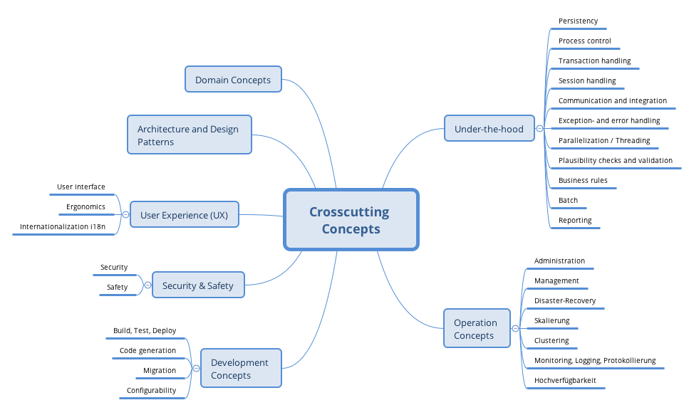
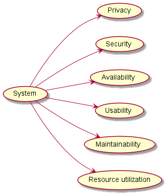
10.1. Quality Tree
10.2. Quality Scenarios
| Quality requirement | Quality scenario | Priority |
|---|---|---|
Privacy |
Our users' data must be extremely protected. The lowest amount of data our application takes, the better. Of course, always taking into account a decentralized delivery. |
High |
Security |
We are going to give as much security as we can, saving the data in a safe way. We will try to prevent any kind of attack or leak. |
High |
Availability |
It is important to give the data to our users whenever they request, trying to reduce the technical failures to the minimal amount of time. |
Medium-High |
Usability |
Whenever the users want to access their information or to save new data, we want the to use our system in an easy way for them. |
Medium-High |
Maintainability |
Because our system will be in a constant develop and change, we want to design our implementation oriented to make this updates easier. |
Medium |
Resource utilization |
Our objective in this part is to use the available resources in an efficient way, trying to complete other goals optimizing the resources we have. |
Low-Medium |
11. Risks and Technical Debts
12. Glossary
| Term | Definition |
|---|---|
Solid |
Solid is a specification that lets people store their data securely in decentralized data stores called Pods. |
TypeScript |
TypeScript is a strongly typed programming language that builds on JavaScript. |
React |
React is an open-source JavaScript library designed for building user interfaces. |
Pod |
Pods are where you store your data. Any kind of data can be stored in a Solid Pod. Once stored in a Pod, you control who can access your data. |
Node.js |
Node.js is a platform built on JavaScript runtime for easily building fast and scalable network applications. |
Firebase |
Platform to develop web applications and also to deploy them. Backend functions can be served from firebase. |
About arc42
arc42, the Template for documentation of software and system architecture.
By Dr. Gernot Starke, Dr. Peter Hruschka and contributors.
Template Revision: 7.0 EN (based on asciidoc), January 2017
© We acknowledge that this document uses material from the arc 42 architecture template, http://www.arc42.de. Created by Dr. Peter Hruschka & Dr. Gernot Starke.